


Software Developer’s Manual 171
Ethernet Interface
8.7.2 Flow Control
Flow control as defined in IEEE specification 802.3x, as well as the specific operation of
asymmetrical flow control defined by 802.3z, are supported. The following registers are defined
for the implementation of flow control:
Flow control is implemented as a means of reducing the possibility of receive buffer overflows
which result in the dropping of received packets, and allows for local control of network
congestion levels. This can be accomplished by sending an indication to a transmitting station of a
nearly-full receive buffer condition at a receiving station.
The implementation of asymmetric flow control allows for one link partner to send flow control
packets while being allowed to ignore their reception. For example, not required to respond to
PAUSE frames.
For the
82541xx and 82547GI/EI, there are two forms of flow control that can be established via
auto-negotiation: symmetric and asymmetric. Symmetric flow control is for point-to-point links;
asymmetric for hub-to-end-node connections. Symmetric flow control allows either node to flow-
control the other. Asymmetric flow control allows a repeater or switch to flow-control a DTE, but
not vice versa
8.7.3 MAC Control Frames & Reception of Flow Control Packets
Three comparisons are used to determine the validity of a flow control frame:
1. A match on the 6-byte multicast address for MAC Control Frames or to the station address of
the device (Receive Address Register 0).
2. A match on the type field.
3. A comparison of the MAC Control Opcode field.
Standard 802.3x defines the MAC Control Frame multicast address as 01_80_C2_00_00_01h. This
address must be loaded into the Flow Control Address Low/High registers (FCAL/H).
The Flow Control Type register (FCT) contains a 16-bit field that is compared against the flow
control packet’s type field to determine if it is a valid flow control packet: XON or XOFF. 802.3x
reserves this value as 8808h. This number must be loaded into the Flow Control Type (FCT)
register.
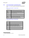
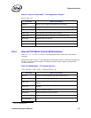
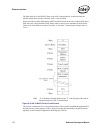
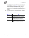
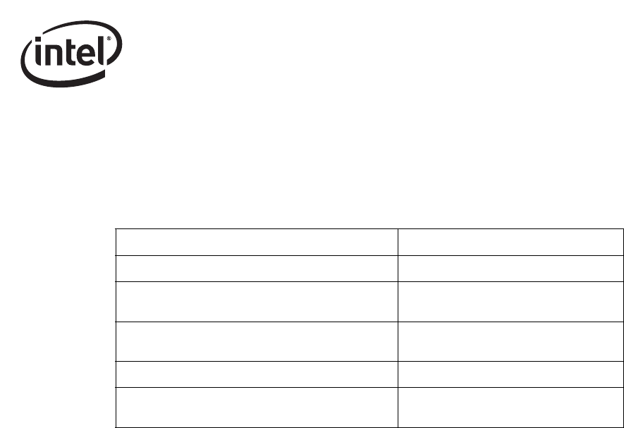
Table 8-10. Flow Control Registers
Register Name Description
Flow Control Address Low, High (FCAL/H) 6-byte flow control multicast address
Flow Control Receive Thresh Hi (FCRTH)
13-bit high water mark indicating receive
buffer fullness
Flow Control Transmit Timer Value (FCTTV)
16 bit timer value to include in transmitted
PAUSE frame
Flow Control Type (FCT) 16-bit field to indicate flow control type
Flow Control Receive Thresh Lo (FCRTL)
13-bit low water mark indicating receive
buffer emptiness