


Software Developer’s Manual 213
Register Descriptions
13.2.2 I/O-Mapped Internal Register, Internal Memory, and Flash
1
To support pre-boot operation (prior to the allocation of physical memory base addresses), all
internal registers, memories, and Flash can be accessed using I/O operations. I/O accesses are
supported only if an I/O Base Address is allocated and mapped (BAR2 or BAR4, see Section 4.1),
the BAR contains a valid (non-zero value), and I/O address decoding is enabled in the PCI/PCIX
configuration.
When an I/O BAR is mapped, the I/O address range allocated opens a 32-byte window in the
system I/O address map. Within this window, two I/O addressable registers are implemented:
IOADDR and IODATA. The IOADDR register is used to specify a reference to an internal register,
memory, or Flash, and then the IODATA register is used as a window to the register, memory or
Flash address specified by IOADDR:
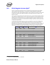
13.2.2.1 IOADDR
The IOADDR register must always be written as a DWORD access (for example, the C/BE#[3:0]
byte enables must all be enabled). Writes that are less than 32 bits are ignored. Reads of any size
return a DWORD of data. However, the chipset or CPU can only return a subset of that DWORD.
For Intel architecture programmers, the IN and OUT instructions must be used to cause I/O cycles
to be used on the PCI bus. Since writes must be to a 32-bit quantity, the source register of the OUT
instruction must be EAX (the only 32-bit register supported by the OUT command). For reads, the
IN instruction can have any size target register, but it is recommended that the 32-bit EAX register
be used.
Since only a particular range is addressable, the upper bits of this register are hard coded to 0b. Bits
31 through 20 are not write-able and always read back as 0b.
At hardware reset (LAN_PWR_GOOD) or PCI Reset, this register value resets to 00h. Once
written, the value is retained until the next write or reset.
13.2.2.2 IODATA
The IODATA register must always be written as a DWORD access when the IOADDR register
contains a value for the Internal Register and Memories (00000h - 1FFFCh). In this case, writes
less than 32 bits are ignored.
1. Not applicable to the 82547GI/EI.
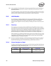
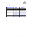
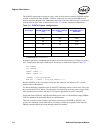
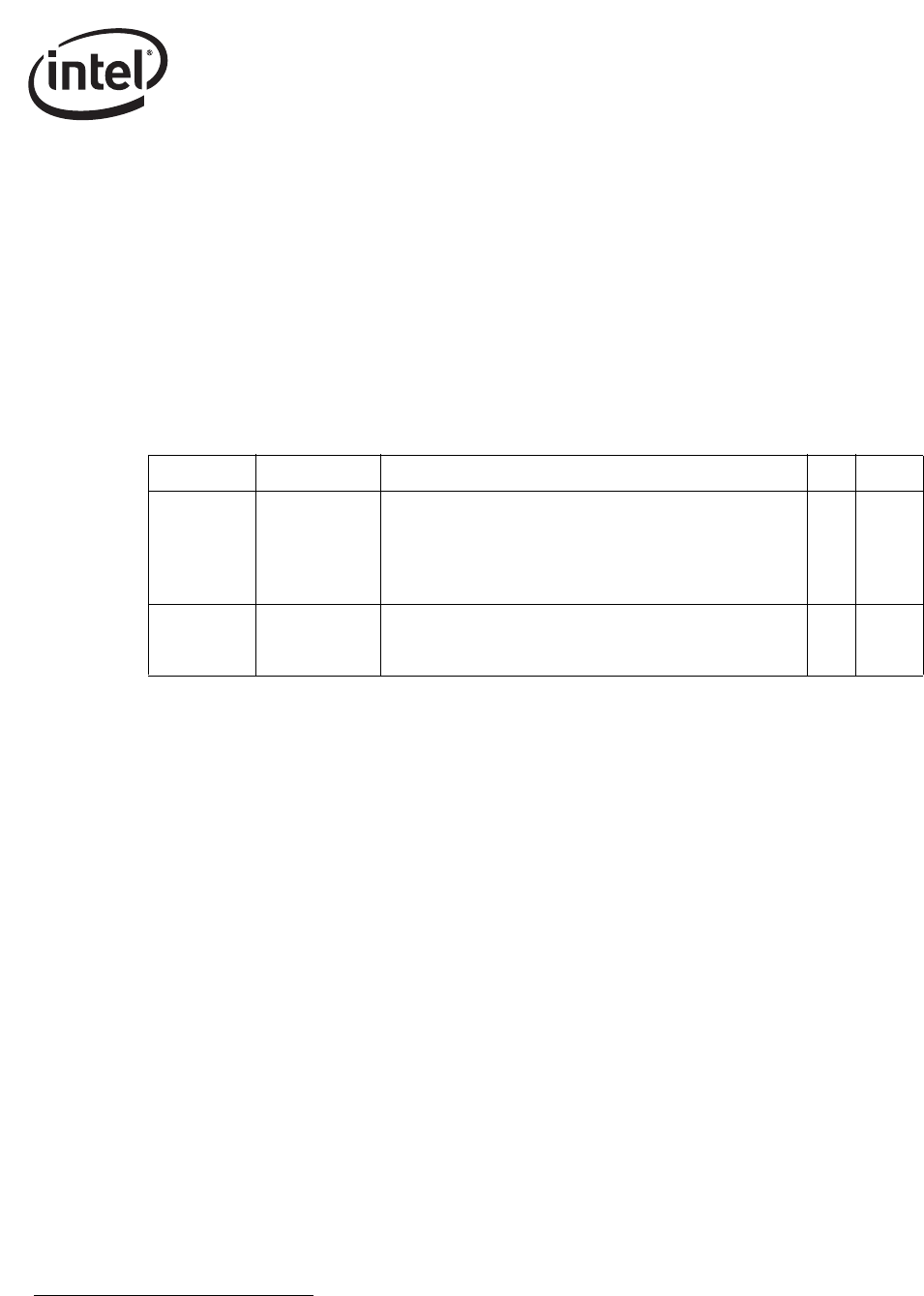
Offset Abbreviation Name RW Size
00000000h IOADDR
Internal Register, Internal Memory, or Flash Location
Address
00000h - 1FFFFh — Internal Registers and Memories
20000h - 7FFFFh — Undefined
80000h - FFFFFh — Flash
RW 4 bytes
00000004h IODATA
Data field for reads or writes to the Internal Register Internal
Memory, or Flash location as identified by the current value
in IOADDR. All 32 bits of this register are read/write-able.
RW 4 bytes