


Software Developer’s Manual 205
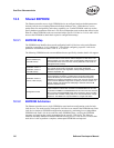
Dual Port Characteristics
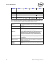
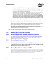
The following fields are implemented unique to each LAN device:
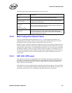
12.2.2 MAC Configuration Register Space
All device control/status registers detailed in Section 13.4, Main Register Descriptions, are
implemented per-LAN device. Each LAN device can be accessed using memory or I/O cycles,
depending on the specific BAR setting(s) established for that LAN device.
Register accesses to each MAC instance are independent. In PCI bus operation, a register access to
one LAN which is retried as a delayed-read requires subsequent accesses to that LAN to retry the
read identically until complete. An outstanding delayed-read for one LAN device does not impact
the Ethernet controller’s ability to accept a register access to the other LAN. Similarly, in PCI-X
bus operation, and register access resulting in a split & split-completion by one LAN device in no
way prevents the other LAN device from accepting and servicing (or splitting) an access to its
register space.
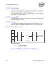
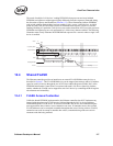
12.2.3 SDP, LED, INT# output
Each LAN device provides an independent set of LED outputs and software-programmable I/O
pins (SDP). Four LED outputs and four SDP pins are provided per LAN device. These pins and
their function are bound to a specific LAN device (eight SDP pins cannot be associated with a
single LAN device, for example).
Each LAN device can use a dedicated pin for signalling interrupts to the system. Two pins, INTA#
and INTB#, exist on the Ethernet controller to signal interrupts by the different LAN devices. The
specific pin used by each LAN is configurable when both LAN devices are enabled.
Device ID
The Device ID reflected for each LAN device can be independently specified
via EEPROM.
Command,
Status
Each LAN device implements its own command/status registers.
Latency Timer,
Cache Line Size
Each LAN device implements these registers uniquely. The system should
program these fields identically for each LAN to ensure consistent behavior
and performance of each device.
Memory BAR,
Flash BAR,
IO BAR,
Expansion ROM BAR
Each LAN device implements its own Base Address registers, allowing each
device to claim its own address region(s).
Interrupt Pin
Each LAN device independently indicates which interrupt pin (INTA# or INTB#)
is used by that Ethernet controller’s MAC to signal system interrupts. The
value for each LAN device can be independently specified via EEPROM, but
only if both LAN devices are enabled.