


Software Developer’s Manual 181
Configurable LED Outputs
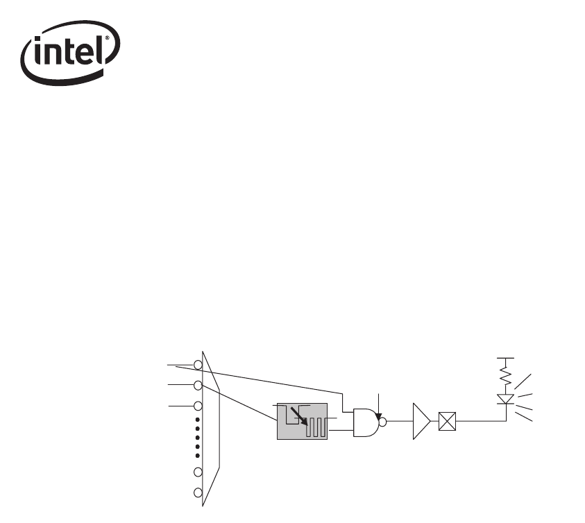
Note: It is especially important to note with respect to the blink-control circuit that:
• the blink circuit, when enabled, exists as the LAST stage of the LED circuitry, after any
(optional) signal inversion
• the blink sequence occurs when the circuit input is asserted low
As a result, it is possible to select combinations of IVRT and BLINK which do not make sense or
produce unexpected results, such as examples previously noted. It is recommended that BLINK
only be selected for indicating ACTIVITY, COLLISION, PAUSED, or the combination LINK/
ACTIVITY signal. events/states, and that IVRT = 0b when blink is selected.
Note: Selecting the LEDCTL.MODE = LINK/ACTIVITY with BLINK = 1b selects a unique LED
output expression (this configuration is meaningful ONLY when IVRT inversion is disabled). In
this configuration, the LED is off (output high) if there is no LINK, on if there is LINK but no
ACTIVITY, and blinking if there is LINK with ACTIVITY.
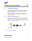
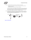
Figure 10-2. Blink Control
LINK_UP
ACTIVITY
BLINK
CONTROL
CIRCUIT
LED
OUTPUT
DRIVER
EXTERNAL
LED
(LINK & NO ACTIVITY)
TOGGLING DURING ACTIVITY