


268 Software Developer’s Manual
Register Descriptions
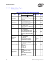
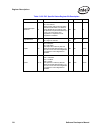
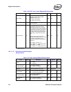
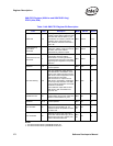
13.4.7.1.16 PHY Interrupt Status Register
PINTS (19d; R)
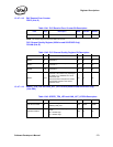
MDI-X Mode 13
Force MDI-X mode. Valid only when
operating in manual mode. (PHY
register 18, bit 12 = 0b.
1b = MDI-X (cross over).
0b = MDI (no cross over).
R/W 0b 0b
Reserved 14
Always read as 0b. Write to 0b for
normal operation.
R/W 0b 0b
Jitter Test Clock 15
This configuration bit is used to enable
the Ethernet controller to drive its
differential transmit clock out through
the appropriate Analog Test (ATEST+/-)
output pads. This feature is required in
order to demonstrate conformance to
the IEEE Clause 40 jitter specification.
When high, it sends Jitter Test Clock
out.
This bit works in conjunction with
internal PHY register 18, bit 15. In order
to have the clock probed out, it is
required to perform the following write
sequence:
PHY register 18, bit15 = 1b
PHY register 31 = 4000h (page select)
PHY register 17 = 0080h
PHY register 31 = 0000h (page select)
R/W 0b 0b
1. The default for this bit is determined by EEPROM configuration bits. If EEPROM bit NCSCRAMB is asserted, then the
default is set to 1b.
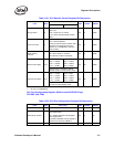
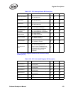
Table 13-36. PHY Port Control Register Bit Description
Field Bit(s) Description Mode HW Rst SW Rst
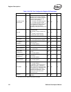
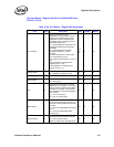
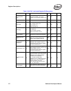
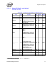
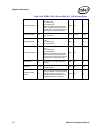
Table 13-37. PHY Interrupt Status Bit Description
Field Bit(s) Description Mode HW Rst SW Rst
Jabber 0
1b = Jabber.
0b = No jabber.
RO,
LH
0b 0b
Polarity Changed 1
1b = Polarity Changed.
0b = Polarity not changed.
RO,
LH
0b 0b
Reserved 3:2 Reserved. Should be set to 00b. RO Always 00b
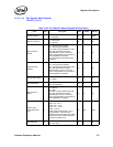
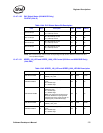
Energy Detect 4
1b = Energy Detect state changed
0b = No state change detected
RO,
LH
0b 0b
Downshift Detected 5
1b = Downshift detected.
0b = No down shift.
RO,
LH
0b 0b
MDI Crossover
Changed
6
1b = Crossover changed.
0b = Crossover not changed.
RO,
LH
0b 0b