376 Software Developer’s Manual
General Initialization and Reset Operation
14.5.1 Signal Interface
The external GMII/MII interface is similar in function to the interface used to communicate
between the MAC and internal PHY. As with use of the internal PHY, the external GMII/MII
interface supports 10/100/1000 Mbps operation, with both half- and full-duplex operation at 10/
100 Mbps, and full-duplex operation at 1000 Mbps. Unlike the communication path to the internal
PHY, the external interface does not provide certain additional control/status interfaces for
automatic hardware link setup and/or power-management
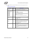
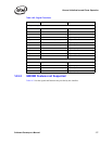
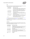
Table 14-2lists the signals, functions, and pins used to provide this interface.
CRS A6
Carrier Sense.
TBI: Undefined.
GMII / MII: This signal indicates traffic activity on the cable, either
incoming or outgoing. This signal is driven by the PHY. CS is not
required to transition synchronously with respect to the RX or TX
clocks. This signal is ignored in full-duplex mode.
Normal Mode: This signal must be connected to VSS except for test
mode.
RX_DATA[9] / RX_ER
RX_DATA[8] / RX_DV
RX_DATA[7]
RX_DATA[6]
RX_DATA[5]
RX_DATA[4]
RX_DATA[3]
RX_DATA[2]
RX_DATA[1]
RX_DATA[0]
A9
D10
B9
C9
D9
E9
E8
C8
A7
B7
Receive Data.
TBI: RX_DATA[9:0] for receive data bus
GMII: RX_DATA[7:0] for receive data bus.
RX_ER signals a receive error. RX_DV is asserted to indicate data is
valid on the interface.
MII: RX_DATA[3:0] for receive data bus.
RX_ER signals a receive error. RX_DV indicates data is valid on the
interface.
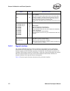
RBC0 / RX_CLK C11
Receive Clock 0.
TBI: RBC0 is receive clock (62.5 Mbps).
GMII: RX_CLK is receive clock (125 Mbps).
MII: RX_CLK is receive clock for 100 Mbps operation (25 Mbps) and
for 10 Mbps operation (2.5 Mbps).
Signal Ball Name and Function


