


Software Developer’s Manual 71
PCI Local Bus Interface
PCI Local Bus Interface 4
The PCI/PCI-X Family of Gigabit Ethernet Controllers are PCI 2.2 or 2.3 compliant devices and
implement the PCI-X Addendum to the PCI Local Bus Specification, Revision 1.0.
Note: The 82540EP/EM, 82541xx, and 82547GI/EI do not support PCI-X mode.
4.1 PCI Configuration
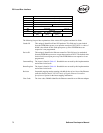
The PCI Specification requires implementation of PCI Configuration registers. After a system
reset, these registers are initially configured by the BIOS, and/or a “Plug and Play” aware
Operating System (OS). Device drivers read these registers to determine what resources (interrupt
number, memory mapping location, etc.) the BIOS and/or OS assigned to the Ethernet controller.
The 82547GI/EI uses a dedicated CSA port for its system bus connection. Logically, it still follows
PCI configuration. However, some configuration parameters, such as cache line, are irrelevant.
Additionally, the 82547GI/EI requires special interrupt configuration in the BIOS (see Section
4.5).
Note: The 82547GI/EI does not support 64-bit addressing.
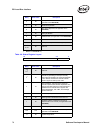
Four different regions of the PCI configuration space are used.
These spaces are linked into a linked list using the Capabilities Pointer field (Cap_Ptr) in the PCI
Configuration section.
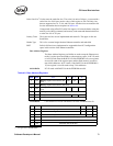
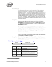
The implementation of the PCI registers for the PCI/PCI-X Family of Gigabit Ethernet Controllers
are listed in Table 4-1:
Table 4-1. Mandatory PCI Registers
Address Item Description
00h-3Ch PCI Section 2.3.1
DCh-E0h PCI Power Management Section 6.3.3
E4h-E8h PCI-X Section 4.1.1
F0h-FCh Message Signaled Interrupt
a
a. Not applicable to the 82541xx and 82547GI/EI.
Section 4.1.3.1
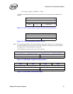
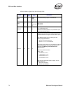
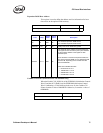
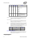
Byte Offset Byte 3 Byte 2 Byte 1 Byte 0
0h Device ID Vendor ID
4h Status Register Command Register
8h Class Code (020000h) Revision ID
Ch BIST (00h)
Header Type
(00h)
Latency
Timer
Cache Line
Size
10h Base Address 0
a
4h Base Address 1
18h Base Address 2