


Software Developer’s Manual 179
Configurable LED Outputs
Configurable LED Outputs 10
10.1 Configurable LED Outputs
1
The PCI/PCI-X Family of Gigabit Ethernet Controller’s MAC implements four output drivers
intended for driving external LED circuits. Each MAC’s four LED outputs can be individually
configured to select the particular event, state, or activity that is indicated on that output. In
addition, each LED can be individually configured for output polarity as well as for blinking vs.
non-blinking (steady-state) indication.
The configuration for LED outputs is specified via the LEDCTL register. In addition, the
hardware-default configuration for two of the LED outputs, LED0/LINK_UP# and LED2/
LINK100# can be specified via EEPROM fields, thereby supporting LED displays configurable to
a particular OEM preference.
10.1.1 Selecting an LED Output Source
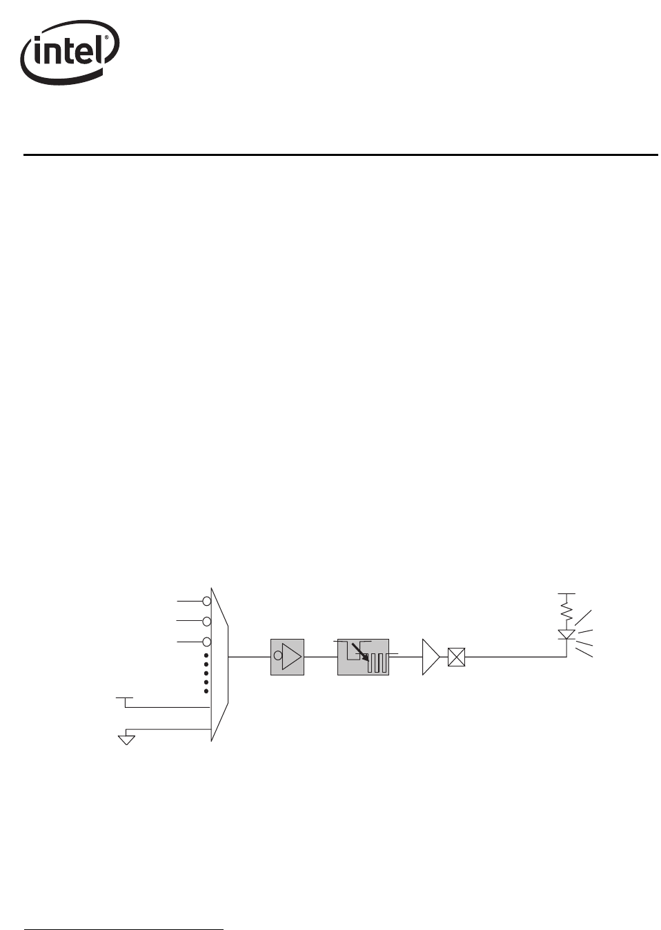
Each of the four LED indications can be independently configured. The LEDCTL register MODE
field corresponding to each LED selects the expression generating the LED output. The LED
outputs are, by default, active low; it is assumed they are connected to the negative side (cathode)
of an external LED. They will, by default, output a low value upon the assertion of the event (such
as COLLISION) or state (such as LINK1000#) selected. Note that the active sense of the LED
outputs can be inverted). See Section 10.1.2 for details.
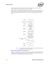
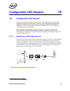
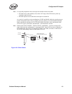
Figure 10-1. Selecting an LED Output Source
1. Section 10 does not apply to the 82544GC/EI.
LINK_UP
ACTIVITY
COLLISION
VCC/LED_OFF
GND/LED_ON
(OPTIONAL)
POLARITY
INVERSION
(OPTIONAL)
BLINK
CONTROL
CIRCUIT
LED
OUTPUT
DRIVER
EXTERNAL
LED