


364 Software Developer’s Manual
Register Descriptions
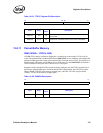
13.8 Diagnostics Registers
The Ethernet controller contains several diagnostic registers. These registers enable software to
directly access the contents of the Ethernet controller’s internal Packet Buffer Memory (PBM), also
referred to as FIFO space. These registers also give software visibility into what locations in the
PBM that the hardware currently considers to be the “head” and “tail” for both transmit and receive
operations.
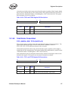
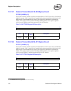
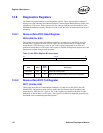
13.8.1 Receive Data FIFO Head Register
RDFH (02410h; R/W)
This register stores the head of the Ethernet controller’s on–chip receive data FIFO. Since the
internal FIFO is organized in units of 64-bit words, this field contains the 64-bit offset of the
current Receive FIFO Head. So a value of “8h” in this register corresponds to an offset of 8
quadwords into the Receive FIFO space. This register is available for diagnostic purposes only, and
should not be written during normal operation.
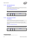
Table 13-142. RDFH Register Bit Description
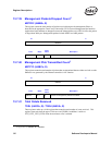
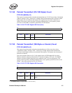
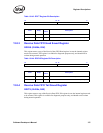
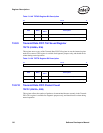
13.8.2 Receive Data FIFO Tail Register
RDFT (02418h; R/W)
This register stores the tail of the Ethernet controller’s on–chip receive data FIFO. Since the
internal FIFO is organized in units of 64-bit words, this field contains the 64-bit offset of the
current Receive FIFO Tail. So a value of “8h” in this register corresponds to an offset of eight
quadwords or into the Receive FIFO space. This register is available for diagnostic purposes only,
and should not be written during normal operation.
31 13 12 0
Reserved FIFO Head
Field Bit(s)
Initial
Value
Description
FIFO Head 12:0 0b Receive FIFO Head pointer.
Reserved 31:13 0b Reads as 0b. Should be written to 0b for future compatibility.