


Software Developer’s Manual 81
PCI Local Bus Interface
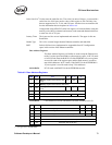
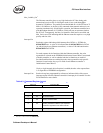
4.1.1.4 PCI-X Status
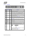
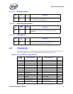
31 29 28 26 25 23 22 21 20 19 18 17 16 15 8 7 3 2 0
Res.
Read
Size
Max.
Split
Rd
Byte
Cplx USC SCD 133 64b Bus Number
Device
Number
Func.
Num.
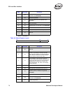
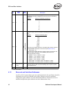
Bits
Read/
Write
Intial
Value
Description
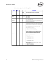
2:0 R 0b
Function Number. This number forms part of the Requester and
Completer IDs for PCI-X transactions.
7:3 R 1Fh
Device Number. The system assigns a device number (other than 0b) to
the Ethernet controller. It forms part of the Requester and Completer IDs
for PCI-X transactions. The Ethernet controller updates this register with
the contents of AD[15:11] on any Type 0 Configuration Write cycle.
15:8 R FFh
Bus Number. This indicates the bus the Ethernet controller is placed on. It
forms part of the Requester and Completer IDs for PCI-X transactions. The
Ethernet controller updates this register with the contents of AD[7:0] on any
Type 0 Configuration Write cycle.
16 R 1b
a
64-bit Device. This indicates the Ethernet controller is a 64-bit device. It
does not indicate the current bus width. It is loaded from the EEPROM
Initialization Control Word 2 (see Section 5.6.12).
17 R 1b
a
133 MHz Capable. A 1b indicates that the Ethernet controller is capable of
operating at 133 MHz in PCI-X mode. A 0b indicates 66 MHz capability.
This bit is loaded from the EEPROM Initialization Control Word 2 (see
Section 5.6.12).
18
read, write 1b
to clear
0b
Split Completion Discarded. (Write 1b to clear) This bit is set if the
Ethernet controller discards a Split Completion because the requester
would not accept it.
19
read, write 1b
to clear
0b
Unexpected Split Completion. (Write 1b to clear) This bit indicates
whether the Ethernet controller received an unexpected Split Completion
with its requestor ID.
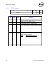
20 R 0b
Device Complexity. A 0b indicates the Ethernet controller is a simple
device. A 1b indicates that the Ethernet controller is a bridge.
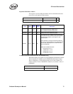
22:21 R 2b
a
Designed Maximum Memory Read Byte Count. Indicates the maximum
memory read byte count the Ethernet controller is designed to generate.
Register
Maximum Byte Count
0 512
1 1024
2 2048
3 4096
The value of this register depends on the Max_Read bit in the EEPROM’s
Initialization Control Word 2 (see Section 5.6.12).
• Max_Read = 0b then value = 2 (2 KB)
• Max_Read = 1b then value = 3 (4 KB)