


Software Developer’s Manual 235
Register Descriptions
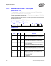
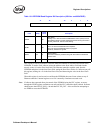
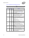
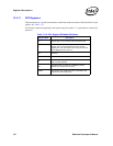
The Ethernet controller allows for up to two externally controlled interrupts. The upper two
software-definable pins, SDP[7:6] (SDP[3:2] for the
82541xx and 82547GI/EI), can be mapped
for use as GPI interrupt bits. These mappings are enabled by the SDPx_GPIEN bits only when
these signals are also configured as inputs via SDPx_IODIR. When configured to function as
external interrupt pins, a GPI interrupt is generated when the corresponding pin is sampled in an
active-high state.
The bit mappings are shown in Table 13-11 for clarity.
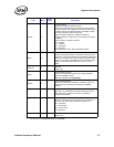
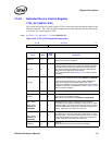
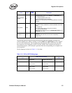
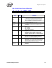
VREG POWER
DOWN
21 0b
Voltage Regulator Power Down (82541xx and 82547GI/EI only)
0b = Normal operation.
1b = Voltage regulators power down.
This bit is initialized from the EEPROM.
Note: This is a reserved bit for all remaining Ethernet controllers.
Set to 0b.
LINK_MODE 23:22 0b
Link Mode. This controls which interface is used to talk to the link.
00b = Direct copper (1000Base-T) interface (GMII/MII internal PHY
mode)
01b = Reserved
10b = Direct Fiber interface (using internal SerDes)
11b = external TBI interface
Note: These are reserved bits for the 82540EP/EM, 82541xx, and
82547GI/EI. Set to 00b
Reserved 31:24 0b
Reserved
Should be written with 0b to ensure future compatibility.
Reads as 0b.
1. These bits are read from the EEPROM
Field Bit(s)
Initial
Value
Description
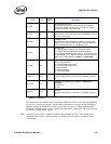
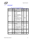
Table 13-11. GPI to SDP Bit Mappings
SDP pin to be used as
GPI
CTRL_EXT field settings
Resulting ICR bit
(GPI)
Directionality Enable as GPI interrupt
7
2
1
SDP7_IODIR
SDP2_IODIR
1
SDP7_GPIEN
SDP2_GPIEN
1
14
6
3
1
SDP6_IODIR
SDP3_IODIR
1
SDP6_GPIEN
SDP3_GPIEN
1
13
1. 82541xx and 82547GI/EI only