


76 Software Developer’s Manual
PCI Local Bus Interface
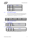
Subsystem ID This value can be loaded automatically from the EEPROM upon power-up or
PCI reset. A value of 1008h is the default for this field upon power-up if the
EEPROM does not respond or is not programmed.
Subsystem Vendor ID
This value can be loaded automatically from the EEPROM upon power-up or
PCI reset. A value of 8086h is the default for this field upon power-up if the
EEPROM does not respond or is not programmed.
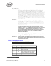
Cap_Ptr The Capabilities Pointer field (Cap_Ptr) is an 8-bit field that provides an offset in
the Ethernet controller’s PCI Configuration Space for the location of the first
item in the Capabilities Linked List. The Ethernet controller sets this bit and then
implements a capabilities list to indicate that it supports PCI Power
Management, PCI-X, and Message Signaled Interrupts
1
. Its value is DCh which
is the address of the first entry: ACPI
2
Power Management.
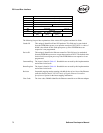
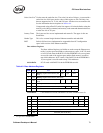
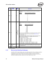
Figure 4-1. Capabilities Linked List
In conventional PCI mode, Message Signaled interrupts can be disabled in the
EEPROM. If disabled, the message signaled interrupts won’t appear on the
linked list and PCI-X’s “Next Pointer” is 0b.
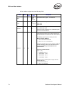
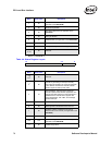
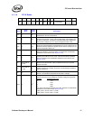
Field Bit(s)
Read/
Write
Initial
Value
Description
Space 2:0 R/W 0 or 2
Indicates the address space where the CIS is
located.
0 = Configuration Space
1 = BAR0
2 = BAR1
3 = BAR2
4 = BAR3
5 = BAR4
6 = BAR5
7 = Expansion ROM
Offset 31:3 R 0 or 4
Offset within the specified address space,
multiplied by eight. When enabled, the value
indicates that the CIS (Card Information
Structure) is at an offset of 4*8, or 32 bytes into
the Flash memory.
1. Not applicable to the 82541xx or 82547GI/EI.
Address Item Next Pointer
DCh-E0h ACPI Power Management E4h
E4h-E8h PCI-X F0h
F0h-FCh Message Signaled Interrupt 00h
2. Not applicable to the 82541ER.