


16 Software Developer’s Manual
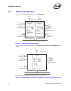
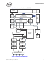
Architectural Overview
2.6 Interrupts
The Ethernet controller provides a complete set of interrupts that allow for efficient software
management. The interrupt structure is designed to accomplish the following:
• Make accesses “thread-safe” by using ‘set’ and ‘clear-on-read’ rather than ‘read-modify-write’
operations.
• Minimize the number of interrupts needed relative to work accomplished.
• Minimize the processing overhead associated with each interrupt.
Intel accomplished the first goal by an interrupt logic consisting of four interrupt registers. More
detail about these registers is given in sections 13.4.17 through 13.4.21.
• Interrupt Cause ‘Set’ and ‘Read’ Registers
The Read register records the cause of the interrupt. All bits set at the time of the read are auto-
cleared. The cause bit is set for each bit written as a 1b in the Set register. If there is a race
between hardware setting a cause and software clearing an interrupt, the bit remains set. No
race condition exists on writing the Set register. A ‘set’ provides for software posting of an
interrupt. A ‘read’ is auto-cleared to avoid expensive write operations. Most systems have
write buffering, which minimizes overhead, but typically requires a read operation to
guarantee that the write operation has been flushed from the posted buffers. Without auto-
clear, the cost of clearing an interrupt can be as high as two reads and one write.
• Interrupt Mask ‘Set’ (Read) and ‘Clear’ Registers
Interrupts appear on PCI only if the interrupt cause bit is a 1b, and the corresponding interrupt
mask bit is a 1b. Software can block assertion of the interrupt wire by clearing the bit in the
mask register. The cause bit stores the interrupt event regardless of the state of the mask bit.
The Clear and Set operations make this register more “thread-safe” by avoiding a ‘read-
modify-write’ operation on the mask register. The mask bit is set to a 1b for each bit written in
the Set register, and cleared for each bit written in the Clear register. Reading the Set register
returns the current value.
Intel accomplished the second goal (minimizing interrupts) by three actions:
• Reducing the frequency of all interrupts (see Section 13.4.17). Not applicable to the
82544GC/EI.
• Accepting multiple receive packets before signaling an interrupt (see Section 3.2.3)
• Eliminating (or at least reducing) the need for interrupts on transmit (see Section 3.2.7)
The third goal is accomplished by having one interrupt register consolidate all interrupt
information. This eliminates the need for multiple accesses.
Note that the Ethernet controller also supports Message Signaled Interrupts as defined in the PCI
2.2, 2.3, and PCI-X specifications. See Section 4.1.3.1 for details.