Software Developer’s Manual 11
Architectural Overview
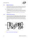
When the Ethernet controller serves as a PCI target, it follows the PCI configuration specification,
which allows all accesses to it to be automatically mapped into free memory and I/O space at
initialization of the PCI system.
When processing transmit and receive frames, the Ethernet controller operates as master on the PCI
bus. As a master, transaction burst length on the PCI bus is determined by several factors, including
the PCI latency timer expiration, the type of bus transfer being made, the size of the data transfer,
and whether the data transfer is initiated by receive or transmit logic.
The PCI/PCI-X bus interfaces to the DMA engine.
2.3.2 82547GI/EI CSA Interface
CSA is derived from the Intel® Hub Architecture. The 82547EI Controller CSA port consists of 11
data and control signals, two strobes, a 66 MHz clock, and driver compensation resistor connec-
tions. The operating details of these signals and the packet data protocol that accompanies them are
proprietary. The CSA port has a theoretical bandwidth of 266 MB/s — approximately twice the
peak bandwidth of a 32-bit 33 MHz PCI bus.
The CSA port architecture is invisible to both system software and the operating system, allowing
conventional PCI-like configuration.
2.3.3 DMA Engine and Data FIFO
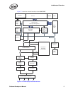
The DMA engine handles the receive and transmit data and descriptor transfers between the host
memory and the on-chip memory.
In the receive path, the DMA engine transfers the data stored in the receive data FIFO buffer to the
receive buffer in the host memory, specified by the address in the descriptor. It also fetches and
writes back updated receive descriptors to host memory.
In the transmit path, the DMA engine transfers data stored in the host memory buffers to the
transmit data FIFO buffer. It also fetches and writes back updated transmit descriptors.
The Ethernet controller data FIFO block consists of a 64 KB (40 KB for the 82547GI/EI) on-chip
buffer for receive and transmit operation. The receive and transmit FIFO size can be allocated
based on the system requirements. The FIFO provides a temporary buffer storage area for frames
as they are received or transmitted by the Ethernet controller.
The DMA engine and the large data FIFOs are optimized to maximize the PCI bus efficiency and
reduce processor utilization by:
• Mitigating instantaneous receive bandwidth demands and eliminating transmit underruns by
buffering the entire out-going packet prior to transmission
• Queuing transmit frames within the transmit FIFO, allowing back-to-back transmission with
the minimum interframe spacing
• Allowing the Ethernet controller to withstand long PCI bus latencies without losing incoming
data or corrupting outgoing data
• Allowing the transmit start threshold to be tuned by the transmit FIFO threshold. This
adjustment to system performance is based on the available PCI bandwidth, wire speed, and
latency considerations


