


14 Software Developer’s Manual
Architectural Overview
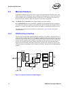
2.3.8 FLASH Memory Interface
The Ethernet controller provides an external parallel interface to a FLASH device. Accesses to the
FLASH are controlled by the Ethernet controller and are accessible to software as normal PCI
reads or writes to the FLASH memory mapping area. The Ethernet controller supports FLASH
devices with up to 512 KB of memory.
Note: The 82540EP/EM provides an external interface to a serial FLASH or Boot EEPROM device. See
Appendix B for more information.
2.4 DMA Addressing
In appropriate systems, all addresses mastered by the Ethernet controller are 64 bits in order to
support systems that have larger than 32-bit physical addressing. Providing 64-bit addresses
eliminates the need for special segment registers.
Note: The PCI 2.2 or 2.3 Specification requires that any 64-bit address whose upper 32 bits are all 0b
appear as a 32-bit address cycle. The Ethernet controller complies with the PCI 2.2 or 2.3
Specification.
PCI is little-endian; however, not all processors in systems using PCI treat memory as little-endian.
Network data is fundamentally a byte stream. As a result, it is important that the processor and
Ethernet controller agree about the representation of memory data. The default is little-endian
mode.
Descriptor accesses are not byte swapped.
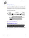
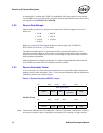
The following example illustrates data-byte ordering for little endian. Bytes for a receive packet
arrive in the order shown from left to right.
01 02 03 04 05 06 07 08 09 0a 0b 0c 0d 0e 0f 10 11 12 13 14 15 16 17 18 19 1a 1b 1c 1d 1e
Example 2-1. Byte Ordering
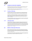
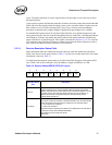
There are no alignment restrictions on packet-buffer addresses. The byte address for the major
words is shown on the left. The byte numbers and bit numbers for the PCI bus are shown across the
top.
Table 2-1. Little Endian Data Ordering
Byte
Address
63 0
76543210
00807060504030201
8100f0e0d0c0b0a09
10 18 17 16 15 14 13 12 11
18 20 1f 1e 1d 1c 1b 1a 19