


Software Developer’s Manual 211
Register Descriptions
Register Descriptions 13
13.1 Introduction
This section details the state inside the PCI/PCI-X Family of Gigabit Ethernet Controllers that are
visible to the programmer. In some cases, it describes hardware structures invisible to software in
order to clarify a concept.
The address space within the Ethernet controller is divided up into eight main categories:
• PCI
• General Configuration and Wakeup
• Interrupt
• MAC Receive
• MAC Transmit
• PHY Receive, Transmit and Special Function
• Statistics
• Diagnostic State (not used in normal operation)
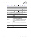
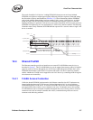
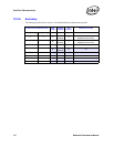
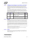
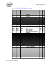
The Ethernet controller’s address space is mapped into four regions with PCI Base Address
Registers described in Table 13-2. These regions are shown as follows.
Both the Flash an Expansion ROM Base Address Registers map the same Flash memory. The
internal registers and memories and Flash can be access through I/O space by doing a level of
indirection, as explained later.
Note: The PHY registers are accessed indirectly through the MDI/O interface described in Section 8.2.
13.2 Register Conventions
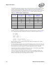
All registers in the Ethernet controller are defined to be 32 bits, should be accessed as 32-bit double
words, and are aligned on a 64-bit boundary. There are exceptions to this rule:
• PCI configuration registers
• I/O space registers (IOADDR and IODATA) are aligned on 32-bit boundaries
• Register pairs where two 32-bit registers make up a larger logical size
• Accesses to Flash memory (through Expansion ROM space or secondary Base Address
Register space) can be byte, word, double word or quadword accesses.
• Reserved bit positions. Some registers contain certain bits that are marked as “reserved.”
These bits should never be set to a value of 1b by software. Reads from registers containing
reserved bits can return indeterminate values in the reserved bit positions unless read values
are explicitly stated. When read, these reserved bits should be ignored by software.
Internal registers and memories (including PHY) Memory 128 KB
Flash (optional) Memory 64 - 512 KB
Expansion ROM (optional) Memory 64 - 512 KB
Internal registers and memories, Flash (optional) I/O 8 Bytes