


134 Software Developer’s Manual
Power Management
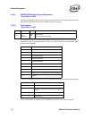
6.3.2.2 Transition From D0a to D3 and Back Without PCI Reset
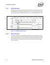
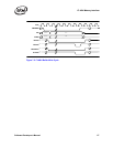
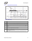
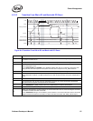
Figure 6-3. Transition from D0a to D3 and Back Without PCI Reset
,B3&,B&/.
567
3&,3LQV
3:5B67$7(>@
5HDGLQJ((3520
5HDG((3520
E
E
'6WDWH
' 'X '
:DNHXS(QDEOHG
0HPRU\$FFHVV(QDEOH
5XQQLQJ
'ZULWH
$30RQO\$Q\PRGH
':ULWH
'D
ELIZDNHXSLVGLVDEOHGELIZDNHXSLVHQDEOHG
EE
*&(,2QO\
Diagram # Notes
1
Writing a 11b to the Power State field of the Power Management Control/Status Register (PMCSR) transitions
the Ethernet controller to D3.
2 The system can keep the Ethernet controller in D3 state for an arbitrary amount of time.
3
To exit D3 state the system writes 00b to the Power State field of the Power Management Control/Status
Register (PMCSR).
4 APM Wakeup mode can be enabled based on what is read in the EEPROM.
5 For the 82544GC/EI, PWR_STATE[1:0] is set to 01b if APM Wakeup is enabled, 00b otherwise.
6 The system can delay an arbitrary time before enabling memory access.
7
Writing a 1b to the Memory Access Enable or I/O Access Enable bit in the PCI Command Register transitions
the Ethernet controller from D0u to D0 state.
For the 82544GC/EI, writing a 1b to the Memory Access Enable or I/O Access Enable bit in the PCI Command
Register transitions the Ethernet controller from D0u to D0 state and asserts both PWR_STATE outputs.