


Receive and Transmit Description
Software Developer’s Manual 35
• The protocol stack calculates the number of packets required to transmit this block based on
the MTU size of the media and required packet headers.
• For each packet of the data block:
— Ethernet, IP and TCP/UDP headers are prepared by the stack.
— The stack interfaces with the software device driver and commands the driver to send the
individual packet.
— The driver gets the frame and interfaces with the hardware.
— The hardware reads the packet from host memory (via DMA transfers).
— The driver returns ownership of the packet to the Network Operating System (NOS) when
the hardware has completed the DMA transfer of the frame (indicated by an interrupt).
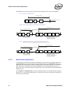
Output packets are made up of pointer–length pairs constituting a descriptor chain (so called
descriptor based transmission). Software forms transmit packets by assembling the list of pointer–
length pairs, storing this information in the transmit descriptor, and then updating the on–chip
transmit tail pointer to the descriptor. The transmit descriptor and buffers are stored in host
memory. Hardware typically transmits the packet only after it has completely fetched all packet
data from host memory and deposited it into the on-chip transmit FIFO. This permits TCP or UDP
checksum computation, and avoids problems with PCI underruns.
3.3.1 Transmit Data Storage
Data are stored in buffers pointed to by the descriptors. Alignment of data is on an arbitrary byte
boundary with the maximum size per descriptor limited only to the maximum allowed packet size
(16288 bytes). A packet typically consists of two (or more) descriptors, one (or more) for the
header and one for the actual data. Some software implementations copy the header(s) and packet
data into one buffer and use only one descriptor per transmitted packet.
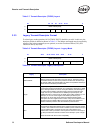
3.3.2 Transmit Descriptors
The Ethernet controller provides three types of transmit descriptor formats.
The original descriptor is referred to as the “legacy” descriptor format. The two other descriptor
types are collectively referred to as extended descriptors. One of them is similar to the legacy
descriptor in that it points to a block of packet data. This descriptor type is called the TCP/IP Data
Descriptor and is a replacement for the legacy descriptor since it offers access to new offloading
capabilities. The other descriptor type is fundamentally different as it does not point to packet data.
It merely contains control information which is loaded into registers of the controller and affect the
processing of future packets. The following sections describe the three descriptor formats.
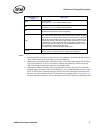
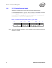
The extended descriptor types are accessed by setting the TDESC.DEXT bit to 1b. If this bit is set,
the TDESC.DTYP field is examined to control the interpretation of the remaining bits of the
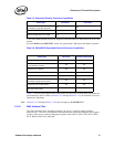
descriptor. Table 3-7 shows the generic layout for all extended descriptors. Fields marked as NR
are not reserved for any particular function and are defined on a per-descriptor type basis. Notice
that the DEXT and DTYP fields are non-contiguous in order to accommodate legacy mode
operation. For legacy mode operation, bit 29 is set to 0b and the descriptor is defined in Section
3.3.3.