


72 Software Developer’s Manual
PCI Local Bus Interface
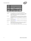
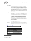
The following list provides explanations of the various PCI registers and their bit fields:
Vendor ID This uniquely identifies all Intel PCI products. This field may be auto-loaded
from the EEPROM at power on or upon the assertion of PCI_RST#. A value of
8086h is the default for this field upon power up if the EEPROM does not
respond or is not programmed.
Device ID This uniquely identifies the Ethernet controller. This field may be autoloaded
from the EEPROM at power on or upon the assertion of RST#. The default value
for this field is used upon power up if the EEPROM does not respond or is not
programmed.
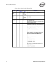
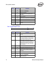
Command Reg. The layout is listed in Table 4-3. Shaded bits are not used by this implementation
and are hard wired to 0b.
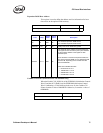
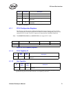
Status Register The layout is listed in Table 4-4. Shaded bits are not used by this implementation
and are hard wired to 0b.
Revision Sequential stepping number starting with 00h for the A0 revision of the Ethernet
controller. Refer to the PCI/PCI-X Family of Gigabit Ethernet Controllers
Specification Update for the latest stepping information.
Class Code The class code, 020000h identifies the Ethernet controller as an Ethernet adapter.
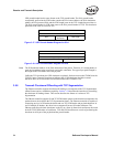
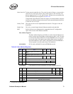
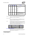
1Ch Base Address 3 (unused)
20h Base Address 4 (unused)
2h4 Base Address 5 (unused)
28h Cardbus CIS Pointer (not used)
2Ch Subsystem ID Subsystem Vendor ID
30h Expansion ROM Base Address
34h Reserved Cap_Ptr
38h Reserved
3Ch
Max_Latency
(00h)
Min_Grant
(FFh)
Interrupt Pin
(01h)
Interrupt Line
a. Refer to Table 4-2.