


74 Software Developer’s Manual
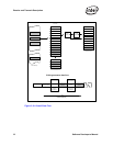
PCI Local Bus Interface
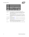
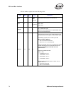
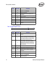
All base address registers have the following fields:
Field Bit(s)
Read/
Write
Initial
Value
Description
Mem 0 R
0b for
mem
1b for I/O
0b indicates memory space. 1b indicates I/O.
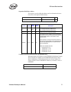
Type 2:1 R
00b for 32-
bit
10b for 64-
bit
Indicates the address space size.
00b = 32-bit
10b = 64-bit
Prefetch 3 R 0b
0b = non-prefetchable space
1b = prefetchable space
Ethernet controller implements non-prefetchable space
since it has read side-effects.
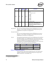
Address 31:0 R/W 0b
The lower bits of the address are hard-wired to 0b. The
upper bits can be written by the system software to set
the base address of the register or flash address space.
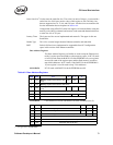
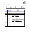
The memory register space is 128K bytes. The
Memory Register BAR has:
• Bits 16:4 are hard-wired to 0b.
• Bits 63:17 or 31:17 are read/write.
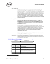
The size of the flash space can very between 64 KB and
512 KB depending on the FLASH size read from the
EEPROM. The Memory Flash BAR has these
characteristics:
Flash Size Valid Bits Zero Bits
(R/W) (RO)
• 64 KB 63/31:16 15:4
• 128 KB 63/31:17 16:4
• 256 KB 63/31:18 17:4
• 512 KB 63/31:19 18:4
The size of the IO register space is 8 bytes. The I/O
Register BAR has:
• Bit 2 hard-wired to 0b
• Bits 31:3 as read/write