


224 Software Developer’s Manual
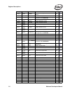
Register Descriptions
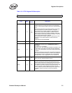
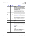
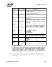
RST 26 0b
Device Reset
0b = normal; 1b = reset. Self clearing.
When set, it globally resets the entire Ethernet controller with
the exception of the PCI configuration registers. All registers
(receive, transmit, interrupt, statistics, etc.), and state machines
are set to their power-on reset values. This reset is equivalent to
a PCI reset, with the one exception being that the PCI
configuration registers are not reset.
To ensure that global device reset has fully completed and that
the Ethernet controller responds to subsequent access, wait
approximately 1 µs after setting and before attempting to check
to see if the bit has cleared or to access any other device
register.
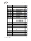
RFCE 27 0b
Receive Flow Control Enable.
When set, indicates that the Ethernet controller responds to the
reception of flow control packets. Reception and responding to
flow control packets requires matching the content of the
Ethernet controller’s FCAL/H and FCT registers. If Auto-
Negotiation is enabled, this bit is set to the negotiated flow
control value. See Section 8.6 for more information about Auto-
Negotiation.
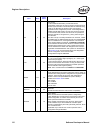
TFCE 28 0b
Transmit Flow Control Enable.
When set, indicates that the Ethernet controller transmits flow
control packets (XON and XOFF frames) based on the receive
FIFO fullness, or when triggered to do so based on external
control pins (XOFF XON pins when FCTRH.XFCE is set). If
Auto-Negotiation is enabled, this bit is set to the negotiated flow
control value. See Auto-Negotiation for more information.
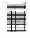
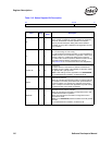
Reserved 29 0b
Reserved.
Should be written with 0b to ensure future compatibility. Read as
0b.
VME 30 0b
VLAN Mode Enable
When set to 1b, all packets transmitted from the Ethernet
controller that have VLE bit set in their descriptor is sent with an
802.1Q header added to the packet. The contents of the header
come from the transmit descriptor and from the VLAN type
register. On receive, VLAN information is stripped from 802.1Q
packets and is loaded to the packet’s descriptor. See Section
9.2 for more details.
Reserved. Should be written with 0b to ensure future
compatibility.
Note: Not applicable to the 82541ER.
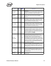
PHY_RST 31 0b
PHY Reset
0b = Normal.
1b = Assert hardware reset to the internal PHY.
The technique is to set the bit, wait approximately 3 µs, then
clear the bit. For the 82547GI/82541GI (B1 stepping), this
register must be used instead of a PHY register.
Note: For the 82546GB, when resetting the PHY through the
MAC, the PHY should be held in reset for a minimum of 10 ms
before releasing the reset signal.
1. 82541xx and 82547GI/EI only.
2. If the signature bits of the EEPROM’s Initialization Control Word 1 match (01b), these bits are read from the EEPROM.
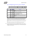
Field Bit(s)
Initial
Value
Description