


Software Developer’s Manual 275
Register Descriptions
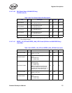
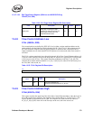
13.4.7.1.20 PHY Global Status (82544GC/EI Only)
PGSTAT (23d; R)
NOTE: Bits 3:0 remain high until the active corresponding interrupt bits are cleared on a read of the PHY
Interrupt Status Register.
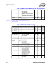
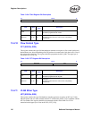
13.4.7.1.21 SPEED_100_LED and SPEED_1000_LED Control (82541xx and 82547GI/EI Only)
(24d; R/W)
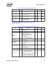
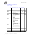
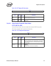
Table 13-44. PHY Global Status Bit Description
Field Bit(s) Description Mode HW Rst SW Rst
Port 0 Interrupt 0
0b = No Interrupt on Port.
1b = Interrupt on Port.
RO 0b 0b
Port 1 Interrupt 1
0b = No Interrupt on Port.
1b = Interrupt on Port.
RO 0b 0b
Port 2 Interrupt 2
0b = No Interrupt on Port.
1b = Interrupt on Port.
RO 0b 0b
Port 3 Interrupt 3
0b = No Interrupt on Port.
1b = Interrupt on Port.
RO 0b 0b
Reserved 15:4 Reserved. Should be set to 0b. RO 0b 0b
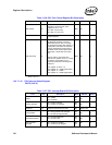
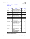
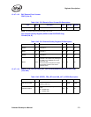
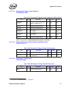
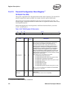
Table 13-45. SPEED_100_LED and SPEED_1000_LED Bit Description
Field Bit(s) Description Mode HW Rst SW Rst
LED Source Select 3:0
MUX the designated input to
SPEED_100_LED.
R/W 0011b 0011b
LED Blink Disable 4
Disable the SPEED_100_LED Blink
Logic.
0b = Enable logic.
1b = Disable logic.
R/W 0b 0b
LED Stretch Disable 5
Disable the SPEED_100_LED
Extension Logic.
0b = Enable logic.
1b = Disable logic.
Note: Only when both the stretch and
blink are disabled the input bypasses
the blink logic and is muxed out with no
sampling (only combinational logic).
R/W 1b 1b
LED Source Select 9:6
Mux the designated input to
SPEED_1000_LED.
R/W 0100b 0100b
LED Blink Disable 10
Disable the SPEED_1000_LED Blink
Logic.
0b = Enable logic.
1b = Disable logic.
R/W 0b 0b