


Chapter 5-Cascading Conferences
Polycom, Inc. 5-3
Basic Cascading
In this topology, a link is created between two conferences, usually running on two different
MCUs. The MCUs are usually installed at different locations (states/countries) to save long
distance charges by connecting each participant to their local MCU, while only the link
between the two conferences is billed as long distance call.
• This is the only topology that enables IP cascading links:
— When linking two conferences using an IP connection, the destination MCU can be
indicated by:
•IP address
•H.323 Alias
— If IP cascading link is used to connect the two conferences, both MCUs must be
located in the same network.
• One MCU can be used as a gateway.
• The configuration can include two Collaboration Servers.
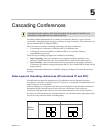
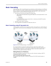
Basic Cascading using IP Cascaded Link
In this topology, both MCUs can be registered with the same gatekeeper or the IP addresses
of both MCUs can be used for the cascading link. Content can be sent across the Cascading
Link.
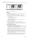
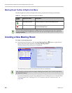
Figure 5-2 Basic Cascading Topology - IP Cascading Link
For example, MCU B is registered with the gatekeeper using 76 as the MCU prefix.
The connection between the two conferences is created when a dial out IP participant is
defined (added) to conference A whose dial out number is the dial-in number of the
conference or Entry Queue running on MCU B.
Dialing Directly to a Conference
Dial out IP participant in conference A dials out to the conference running on MCU B
entering the number in the format:
[MCU B Prefix/IP address][conference B ID].
For example, if MCU B prefix is 76 and the conference ID is 12345, the dial number is
7612345.