


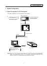

1. System Configuration
- 2 -
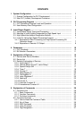
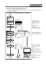
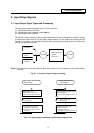
1.2 User PLC (Ladder) Development Procedure
The procedure for creating the user PLC, used to control the control target (machine) built into the
control unit, is shown below.
Determination of
machine
Determination of
CNC and PLC
specifications
Determination of the
numbers of I/O points
Assignment of I/O
signals
Assignment of
internal relays
Programming
Start
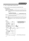
Device Name
Comment
X0 X-OT X-axis OT
X1 Y-OT Y-axis OT
X2 Z-OT Z-axis OT
Commercially available
spreadsheet tool
GX Developer
Onboard
Procedure Personal Computer CNC Unit
GX Developer
Completion
Test operation by
CNC unit
NO
YES
NO
YES
GX Developer
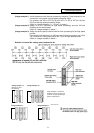
#( ) ( )
[BACKUP]
#1 BACKUP #######
#2 RESTORE #########
PARAM 3.2/2
Memory cassette
Is test operation
OK?
Debugging operation
Program correction
Printout
Data save
Is debugging
complete?
Program data
Binary data
BACKUP screen
DATA IN/OUT screen
The data created with the
commercially available
spreadsheet tool can be
used as ladder comment
data.
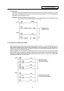
Use GX Developer for
programming.
After completion, download
the data through RS-232C.
Perform monitoring/correction
with GX Developer's online
function or onboard function.
Program data:
Saved using GX Developer
Binary data:
Saved using DATA IN/OUT
screen
Printout to a commercial
printer connected with the
personal computer from GX
Developer.
Excute the ROM backup
operation on the BACKUP
screen.
Excute the binary data output
on the DATA IN/OUT screen.
(F-ROM)