


9. Exclusive Commands
- 213 -
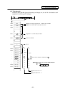
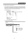
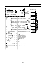
ACT
Rn
S.ROT
K1
Mm Rm
0:CW
1:CCW
R number to specify rotary body
index cycles (R511 in this example)
Top of control data buffer
(R500 in this example)
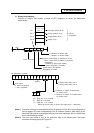
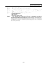
PLS M100
S.ROT K1 R500 R511
M200
<= R510 H0F
Completion circuit
X34
M100
X238
M202
(M203)
M200
M200
M201
M202
M203
Y10
Y11
CW
CCW
M1000
Y226
Auxiliary function completed
On-signal after PLC1 scan
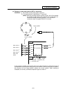
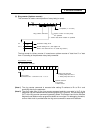
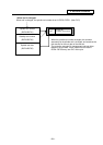
R No. to store the target position
R No. to store the output position
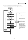
Parameter is set.
Rotary body index cycles
are set.
CW or CCW is determined by the
ROT command.
Strobe rising signal created
The current value is set at R512.
Error check
When required
Stop signal created (Note 1)
(target value = current value)
Stop signal created (Note 1)
(number of steps = 0)
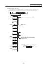
MOV K510 R500
X238
X238
X238
M1000
M1000
R No. to store the parameter
R No. to store the current position
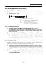
1~6 (BCD)
0
510
36
513
1~6
(number of
output steps)
R36
R37
R500
File register (R) map
T command
(from CNC)
M1000
8
6
512
(Note 5)
(Note 5)
R501
R502
R503
R510
R511
R512
R513
MOV K512 R501
MOV K36 R502
MOV K513 R503
MOV H8 R510
MOV K6 R511
0 ~3
MOV K1X30 R512
= R36 R512
=
K0
R513