


DECO
- 179 -
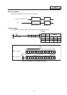
Program example
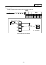
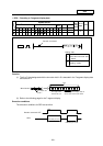
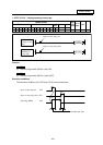
(1) Program to decode the three bits 0 to 2 of R20, and turn the bits corresponding in D100 ON.
Coding
No. of
steps
Com-
mand
Device
10 LD X0
11 DECO R20 D100 K3
DECO
D100
R20
K3
X0
10
16
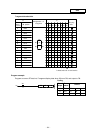
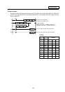
B15B14 B13 B12 B11B10 B9 B8 B7 B6 B5 B4 B3 B2 B1 B0
000001 000000 0111
B15B14 B13 B12 B11B10 B9 B8 B7 B6 B5 B4 B3 B2 B1 B0
0000 0100
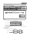
When bit 0 to 2 data is binary and 6.
Interpreted as 0
Does not change
Only bit 6 of bits 0 to 7 is turned ON.
R20
D100
(Note 1) The D100 bit 0 turns ON when the B0 to B2 of R20 are 0.
(Note 2) The D100 details remain the same even if X0 turns OFF.
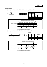
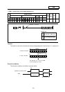
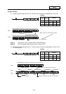
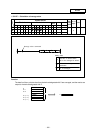
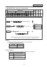
(2) Program to decode the eight bits 0 to 7 of R20, and turn the bits corresponding in D100 to D115
(2
8
= 256 bits) ON.
Coding
No. of
steps
Com-
mand
Device
10 LD X0
11 DECO R20 D100 K8
DECO D100R20 K8
X0
10
16
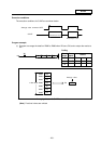
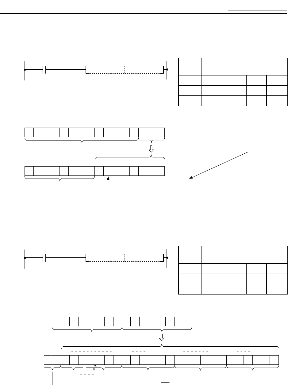
B15B14 B13 B12 B11B10 B9 B8 B7 B6 B5 B4 B3 B2 B1 B0
000000110010 1000
B255 B48 B47 B34B33B32B31 B2 B1 B0
0100 0000
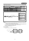
When bit 0 to 7 data is binary and 33.
interpreted as 0
Does not change
Only bit 33 of bits 0 to 255 is turned ON.
R20
D100
B17 B16 B15
D100D101D102D103D115
00000 000000000000
D115
to