


5. Explanation of Devices
- 16 -
5.3 Detailed Explanation of Devices
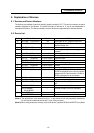
5.3.1 Input/output X, Y
Input/output X and Y are a window for executing communication with the PLC and external device or
CNC.
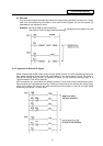
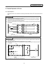
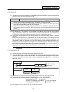
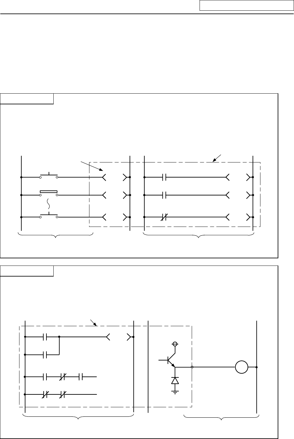
Input X
(a) This issued commands or data from an external device such as a push-button, changeover
switch, limit switch or digital switch to the PLC.
(b) Assuming that there is a hypothetical relay Xn built-in the PLC per input point, the program
uses the "A" contact and "B" contact of that Xn.
(c) There is no limit to the No. of "A" contacts and "B" contacts of the input Xn that can be used in
the program.
PB1
LS2
PB16
X10
X11
X1F
Input circuit
Program
X10
X11
X1F
PLC
Hypothetical relay
(d) The input No. is expressed with a hexadecimal.
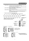
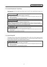
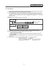
Output Y
(a) This outputs the results of the program control to the solenoid, magnetic switch, signal lamp or
digital indicator, etc.
(b) The output can be retrieved with the equivalent of one "A" contact.
(c) There is no limit to the No. of "A" contacts and "B" contacts of the output Yn that can be used in
the program.
Output circuit
Y10
Y10
Y10
PLC
Program
Y10
24V
Load
(d) The output No. is expressed with a hexadecimal.