


10. PLC Help Function......................................................................................... 252
10.1 Alarm Message Display............................................................................ 253
10.1.1 Interface ............................................................................................. 253
10.1.2 Screen Display ................................................................................... 255
10.1.3 Message Creation .............................................................................. 256
10.1.4 Parameters......................................................................................... 259
10.2 Operator Message Display....................................................................... 261
10.2.1 Interface ............................................................................................. 261
10.2.2 Operator Message Preparation.......................................................... 262
10.2.3 Operator Message Display Validity Parameter................................... 262
10.3 PLC Switches........................................................................................... 263
10.3.1 Explanation of Screen ........................................................................ 263
10.3.2 Explanation of Operation.................................................................... 264
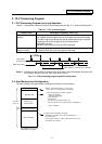
10.3.3 Signal Processing............................................................................... 265
10.3.4 Switch Name Preparation................................................................... 269
10.4 Key Operation by User PLC..................................................................... 270
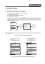
10.4.1 Key Data Flow.................................................................................... 270
10.4.2 Key Operations That Can Be Performed............................................ 270
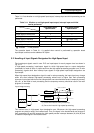
10.4.3 Key Data Processing Timing .............................................................. 271
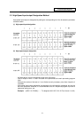
10.4.4 Layout of Keys on Setting and Display Unit ....................................... 272
10.4.5 List of Key Codes ............................................................................... 273
10.5 Load Meter Display .................................................................................. 274
10.5.1 Interface ............................................................................................. 274
10.6 External Machine Coordinate System Compensation .............................. 276
10.7 User PLC Version Display........................................................................ 277
10.7.1 Interface ............................................................................................. 277
11. PLC Axis Control ........................................................................................... 279
11.1 Outline...................................................................................................... 279
11.2 Specifications ........................................................................................... 279
11.2.1 Basic Specifications ........................................................................... 279
11.2.2 Other Restrictions .............................................................................. 280
11.3 PLC Interface ........................................................................................... 281
11.3.1 S.DDBS Function Command.............................................................. 281
11.3.2 Control Information Data .................................................................... 282
11.3.3 Control Information Data Details ........................................................ 283
11.3.3.1 Commands ................................................................................ 283
11.3.3.2 Status ........................................................................................ 284
11.3.3.3 Alarm No.................................................................................... 291
11.3.3.4 Control Signals (PLC axis control information data) .................. 292
11.3.3.5 Axis Designation........................................................................ 294
11.3.3.6 Operation Mode......................................................................... 294
11.3.3.7 Feedrate .................................................................................... 295
11.3.3.8 Movement Data ......................................................................... 295
11.3.3.9 Machine Position ....................................................................... 296
11.3.3.10 Remaining Distance.................................................................. 296
11.3.4 Reference Point Return Near Point Detection.................................... 297
11.3.5 Handle Feed Axis Selection ............................................................... 298
12. Appendix ....................................................................................................... 299
12.1 Example of Faulty Circuit ......................................................................... 299