6. Explanation of Commands
- 26 -
6. Explanation of Commands
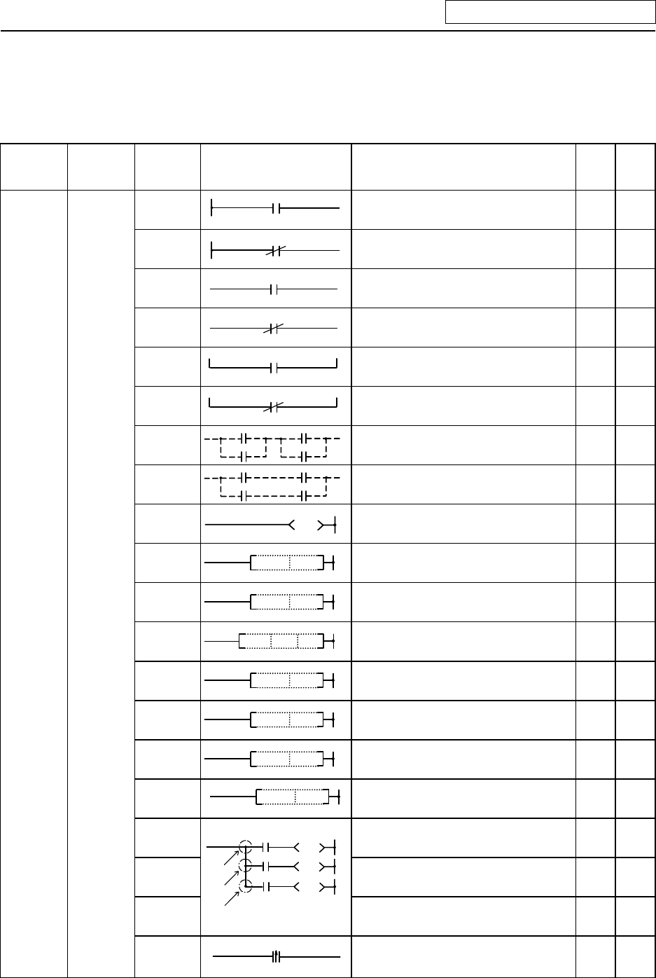
6.1 Command List
6.1.1 Basic Commands
Class
Process
unit
Command
sign
Symbol
Process details
No.
of
steps
Page
LD
Start of logic operation
(A contact operation start)
1 42
LDI
Start of logic denial operation
(B contact operation start)
1 42
AND
Logical AND
(A contact serial connection)
1 44
ANI
Logical AND denial
(B contact serial connection)
1 44
OR
Logical OR
(A contact parallel connection)
1 46
ORI
Logical OR denial
(B contact parallel connection)
1 46
ANB
AND between logical blocks (Serial
connection between blocks)
1 48
Basic
command
Bit
ORB
OR between logical blocks
(Parallel connection between blocks)
1
50
OUT
Device output
1~3 52
SET
SET
D
Device set
1 58
RST
RST
D
Device reset
1~2 60
MC
M
nD
Master control start
2 62
MCR
MCR
n
Master control release
1 62
PLS
PLS D
Generate one cycle worth of pulses at rising
edge of input signal
2 64
PLF
PLF
D
Generate one cycle worth of pulses at falling
edge of input signal
2 64
SFT
SFT
D
Device 1-bit shift
4 66
MPS
Registration of logical operation result
1 68
MRD
Read of operation results registered in MPS
1 68
MPP
MPS
MRD
MPP
Reading and resetting of operation results
registered in MPS
1 68
DEFR
(ANDP)
Generate one cycle worth of pulses to
oper-ation results at rising edge of input
signal (Note)
1 70
(Note) The "ANDP" command is alternatively used for the MELSEC PLC development tool (GX
Developer).


