


9. Exclusive Commands
- 244 -
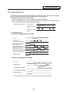
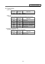
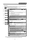
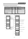
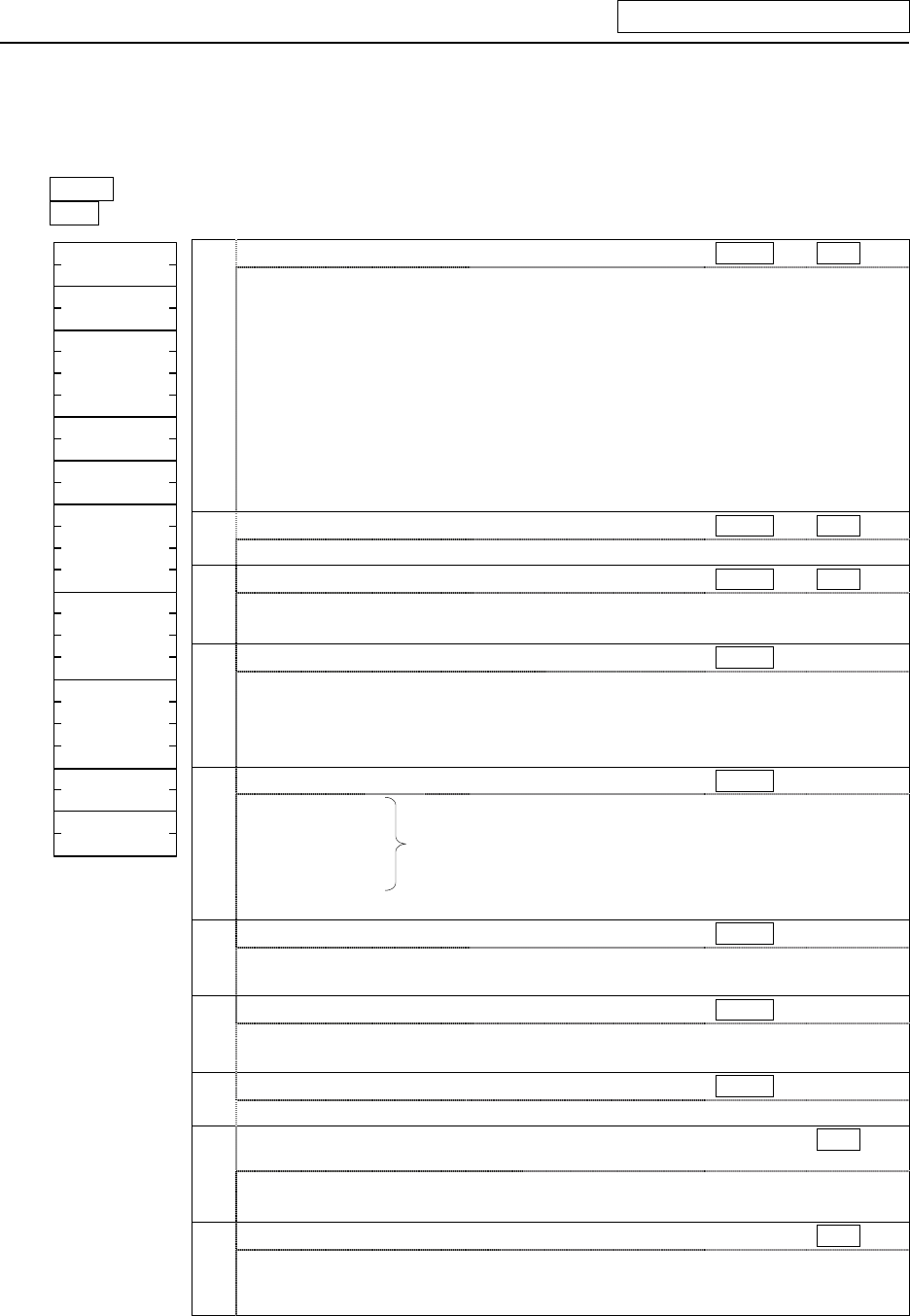
(2) Control data
Data to be used differs depending on whether the compensation value sequential update method is
applied or compensation amount fixed method is applied.
Update : Specify with the compensation value sequential update method
Fixed : Specify with the compensation value fixed method
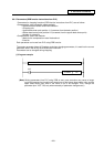
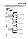
a: Control status (Rn)
Update
Fixed
bit0 : Set to "1".
bit1 : Set to "0".
bit2 to bit8 : Not used
bitF : Error occurred
This turns ON if an alarm occurrs when the chopping parameter valid signal is
turned ON. The details of error is notified with bit9 to C. (Note)
bit9 : Chopping error
bitA : Chopping specifications is not available
bitB : Compensation method is set to other than 0/1
bitC : Multiple chopping axes are specified
b: Section No. (Rn+1)
Update
Fixed
This sets 0100(HEX).
c: Sub-section No. (Rn+2[low], Rn+3[high])
Update
Fixed
0000(HEX) : Compensation value sequential update method
0001(HEX) : Compensation value fixed method
d: Rapid traverse override valid/invalid (Rn+4)
Update
This sets the rapid traverse override valid/invalid in respect to the movement speed
between the basic position and the upper dead center point.
0 : Invalid
1 : Valid
e: Chopping axis designation (Rn+5)
Update
bit0 : 1st axis
bit1 : 2nd axis
bit2 : 3rd axis
bit3 : 4th axis
Select any one of the existing axes using bit.
When no axis is specified, the axis whose base specification
parameter "chop_ax" is "1" (the smallest No. of axis) is
selected.
bit4 F : Not used (Set to "0".)
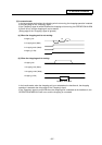
f: Upper dead center point (Rn+6[low], Rn+7[high])
Update
This sets the movement amount of basic position
→ upper dead center point with the
code. Use the setting and display unit (#1003 iunit) for setting.
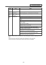
g: Bottom dead center point (Rn+8[low], Rn+9[high])
Update
This sets the distance of upper dead center point
→ bottom dead center point with the
code. Use the setting and display unit for setting.
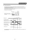
h: Number of cycles (Rn+10[low], Rn+11[high])
Update
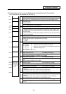
Rn
Rn+1
Rn+2
Rn+4
Rn+5
Rn+6
Rn+8
Rn+12
Rn+10
Rn+13
a
b
c
d
e
f
g
i
j
h
This sets the number of cycles for chopping cycle. (Unit: Number of cycles/min)
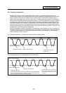
I: Operation mode with the
compensation value fixed method
(Rn+12)
Fixed
0000(HEX) : Playback mode
0001(HEX) : Record mode
j: Data No. (Rn+13)
Fixed
This specifies what number data (n-th data) from the head of the record area
(specified by the parameter) to be used. (Both the record mode and playback mode
must be specified. 1st data area is specified with 0.)
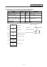
(Note) If an alarm occurs when the chopping parameter valid signal is turned ON, Rn bit is turned
ON. Alarm details are output to the chopping error No. (R554), as well.