


5. Explanation of Devices
- 15 -
5. Explanation of Devices
5.1 Devices and Device Numbers
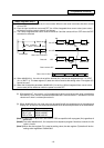
The devices are address symbols to identify signals handled in PLC. The device numbers are serial
numbers assigned to the devices. The device numbers of devices X, Y and H are represented in
hexadecimal notation. The device numbers of other devices are represented in decimal notation.
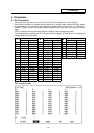
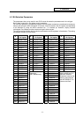
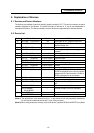
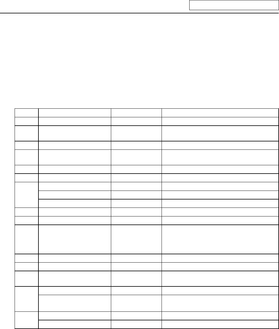
5.2 Device List
Device Device No. Unit Details
X* X0~XABF (2752 points) 1 bit Input signal to PLC. Machine input, etc.
Y* Y0~YDEF (3584 points) 1 bit Output signal from PLC.
Machine output, etc.
M M0~M8191 (8192 points) 1 bit Temporary memory
F F0~F127 (128 points) 1 bit Temporary memory, alarm message
interface
L L0~L255 (256 points) 1 bit Latch relay (backup memory)
SM* SM0~SM127 (128 points) 1 bit Special relay
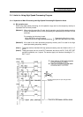
T T0~T15 (16 points) 1 bit or 16 bits 10ms unit timer
T16~T95 (80 points) 1 bit or 16 bits 100ms unit timer
T96~T103 (8 points) 1 bit or 16 bits 100ms unit integrating timer
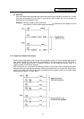
C C0~C23 (24 points) 1 bit or 16 bits Counter
D D0~D1023 (1024 points) 16 bits or 32 bits Data register for arithmetic operation
R* R0~R8191 (8192 points) 16 bits or 32 bits File register. R500 to R549 and R1900 to
R2799 are released to the user for interface
between the PLC and controller. R1900 to
R2799 are backed up by the battery.
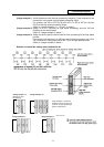
Z Z0~Z1 (2 points) 16 bits Index of D or R address (±n)
N N0~N7 (8 points) — Master control nesting level
P* P0~P255 (256 points) — Label for conditional jump and subroutine
call
K K-32768~K32767 — Decimal constant for 16-bit command
K-2147483648~
K2147483647
— Decimal constant for 32-bit command
H H0~HFFFF — Hexadecimal constant for 16-bit command
H0~HFFFFFFFF — Hexadecimal constant for 32-bit command
(Note 1) The applications of the devices having a * in the device column are separately determined.
Do not use the undefined device Nos., even if they are open.
(Note 2) When using temporary memory such as M device, separate READ and WRITE every 8bits.