


9. Exclusive Commands
- 249 -
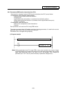
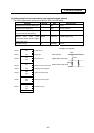
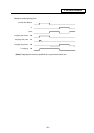
9.6.6 Example of chopping control by program command
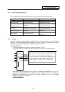
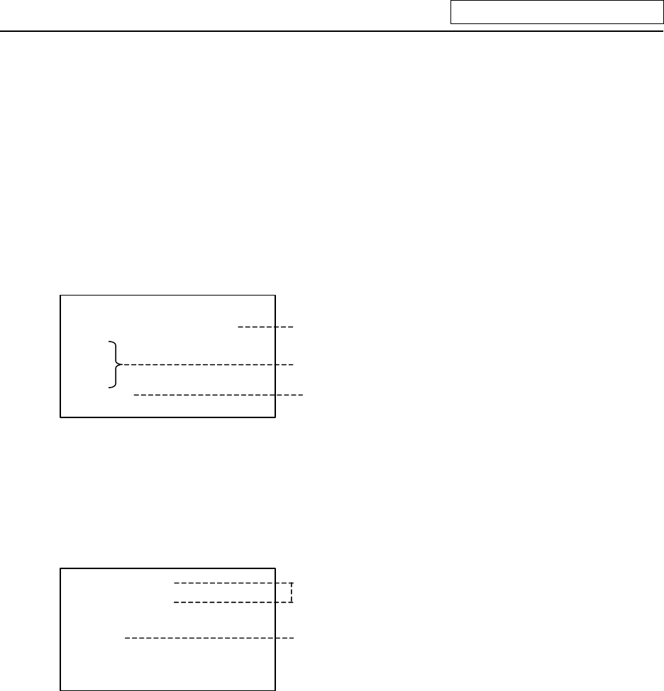
In the example given below, the upper dead center point (increment from the basic position), bottom
dead center point (increment from the upper dead center point), and number of cycles (times/min) are
set using G code macro.
The above data is set to the local variables by G code macro. The local variable data is read by the
ladder upon execution of M code (M10). Then, chopping is started upon DDB function instruction. The
chopping is stopped by the ladder upon execution of M code (M11).
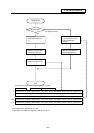
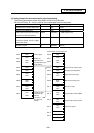
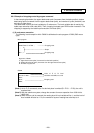
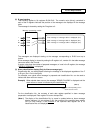
(1) G code macro execution
The following is an example in which O9000 is defined as the sub-program of G200 (G65 macro
type).
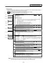
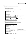
:
G200 Z-20. Q-10. R50. ;
:
:
:
M11 ;
#26=#26*1000 ;
#17=#17*1000 ;
G04 ;
M10 ;
M99 ;
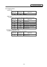
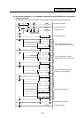
A
rgument of G200
Z : Upper dead center point (Increment from the basic position)
Q : Bottom dead center point (Increment from the upper dead center point)
R : Number of cycles/min.
Main program
O9000
Chopping start
Shape
Chopping stop
Value of Z, Q, R: local
variables set to #26, #17, #18
Chopping start
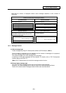
(Note 1) As for Z, Q commands, even if a decimal place is omitted (Ex. Z-20. → Z-20), the unit is
remained mm.
(Note 2) With the submicron system, change the constant for macro operation from 1000-fold to
10000-fold.
(Note 3) When a macro call is executed, the nesting level of local variable will be 1, and the level of
local variable will also be 1. So, the number of layers of nesting has to be kept to 4.