


9. Exclusive Commands
- 229 -
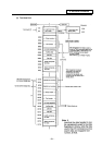
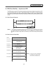
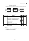
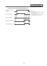
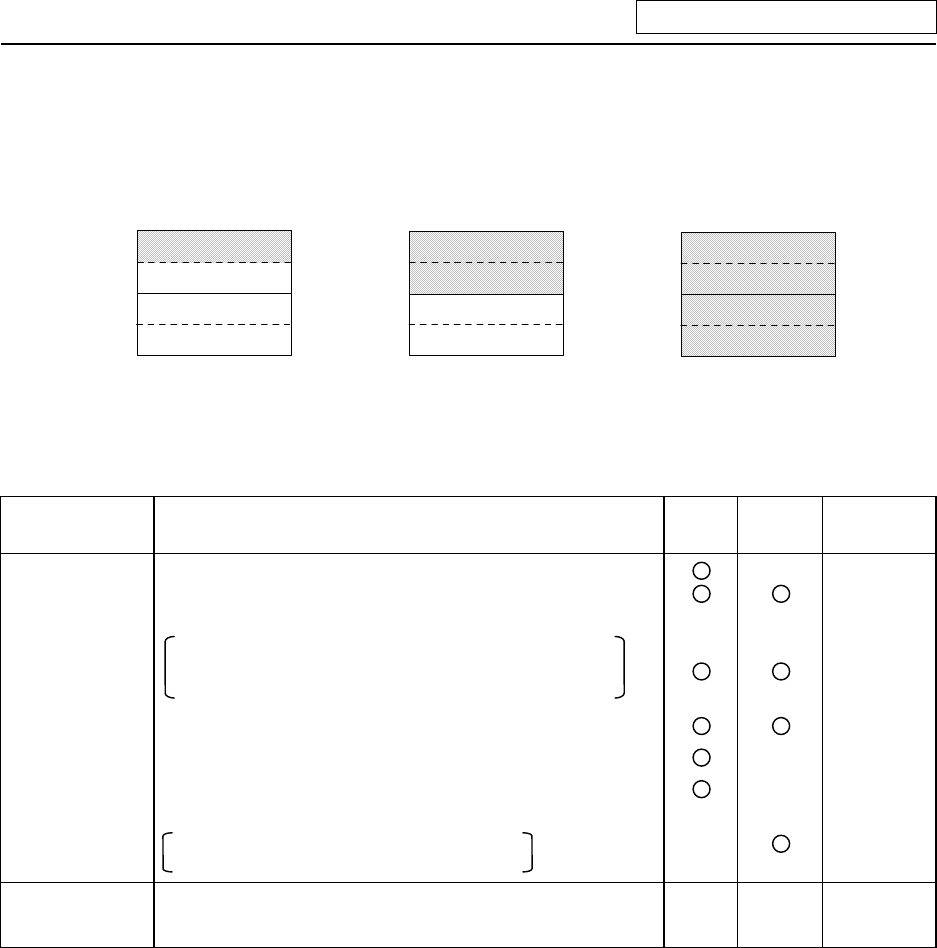
(6) Read/write data (Rn+6, Rn+7), (Dn+6, Dn+7)
(LOW) (HIGH) (LOW) (HIGH)
When data is read, the controller outputs data specified by PLC. When data is written, PLC sets
the data to be written.
Rn+6
Rn+7
(Dn+7)
(Dn+6)
Rn+6
Rn+7
(Dn+7)
(Dn+6)
Rn+6
Rn+7
(Dn+7)
(Dn+6)
1-byte data
2-byte data 4-byte data
H
L
H
L
The effective portion of data varies depending on the data size. (Hatched portion)
When read is specified the sign of 1-byte or 2-byte is extended to four bytes.
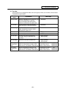
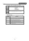
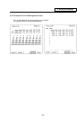
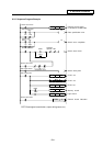
The main data that can be referenced by using the DDB function is listed below.
Specification
item
Contents Read Write Remarks
Asynchronous Current position in work coordinate, machine coordinate
system, length, radius offset amount
—
Parameters
Maximum rotation speed of spindle, second, third,
and fourth reference position coordinates,
stored stroke limit, coordinate system offset, etc.
User macro variables
Modal data of G code, etc.
—
Controller alarm number
—
Compensation function
External work coordinate system input,
external tool compensation input
—
Synchronous External search — —
PLC axis control, etc. — —
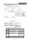
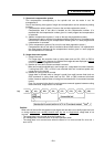
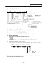
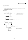
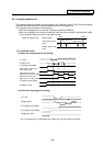
Caution:
The DDBA command is issued after setting necessary data such as control signal and large and
sub-classification numbers to the buffer (Rn or Dn). A read or write of the control signal is
specified only once before execution of the DDBA command to prevent error codes stored in
high-order bits by the CNC from being erased.