


5. Explanation of Devices
- 20 -
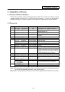
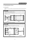
5.3.5 Counter C
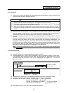
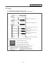
(1) The counter counts up and detects the rising edge of the input conditions. Thus, the count will not
take place when the input conditions are ON.
Counter C
(a) The value is set with a decimal, and can be designated from 1 to 32767. The data register (D)
data can also be used as the setting value. File register (R) cannot be used.
(b) The counter count value will not be cleared even if the input conditions turn OFF. The counter
count value must be cleared with the RST command.
(c) When the bit selection parameter is set, the counter current value (count value) will be held
even when the power is turned OFF. Note that some can not be held depending on the version
of CNC.
(2) With the device C, the contact • coil is handled as bit device, and the current value (counter
value) is handled as word device. In the function commands described after, the word device C
indicates the current value (counter value) even if there is no description about it.
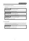
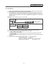
(3) The counter setting value can be set with the setting and display unit using device C. (Variable
counter)
Whether the setting value (Kn) programmed with the sequence program or the setting value set
from the setting and display unit is valid is selected with the bit selection parameters. The
changeover is made in a group for C0 to C23. Even when set from the setting and display unit,
the setting value (Kn) program will be required in the sequence program. However, the Kn value
will be ignored. When the data register (D) is used for the setting value, the data register (D)
details will be used as the setting value regardless of the parameter.
(Note) The setting value for device C24 to C127 of counter C cannot be set from the setting and
display unit.
5.3.6 Data Register D
(1) The data register is the memory that stores the data in the PLC.
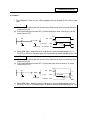
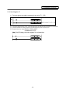
(2) The data register has a 1-point 16-bit configuration, and can be read and written in 16-bit units.
To handle 32-bit data, two points must be used. The data register No. designated with the 32-bit
command will be the low-order 16-bit, and the designated data register No. +1 will be the
high-order 16-bit.
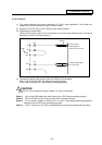
Low-order 16-bit
Circuit example
Data storage
The X0 to 1F data is
stored in D0,1.
D1
D0
~
Higth-order 16-bit
(X1F X10)
(XF X0)
0
DMOV K8X0
D0
~
(3) The data that is stored once in the sequence program is held until other data is stored.
(4) The data stored in the data register is cleared when the power is turned OFF.
(5) Values that can be stored: Decimal -32768 to 32767 For 16-bit command
Hexadecimal 0 to FFFF
(Using Dn)
Decimal -2147483648 to 2147483647 For 32-bit command
Hexadecimal 0 to FFFFFFFF
(Using Dn+1, Dn)
(6) Data registers D0 to D1023 are all user release data registers.