


10. PLC Help Function
- 265 -
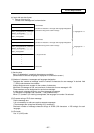
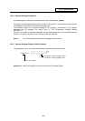
The table below shows the message displayed during operation on the PLC switch screen.
No.
Message
Explanation
Remedy
E01
SETTING
ERROR
A number outside the allowable
setting range from 1 to 32 is
specified in # ( ).
Specify a valid number within the
range.
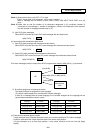
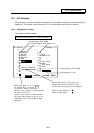
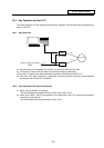
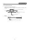
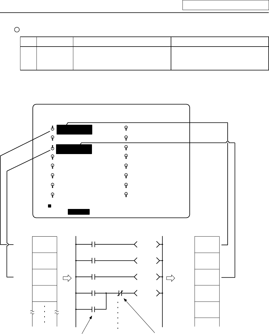
10.3.3 Signal Processing
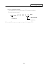
4
Input Output
X140
X141
X142
X143
1
0
1
0
1
0
1
0
Y160
Y161
Y162
Y163
0Y164
X8
X143
X142
X141
X140 Y160
Y161
Y162
Y163
X9
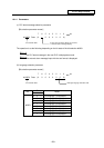
External switch
Condition for validity
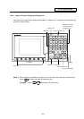
The characters are highlighted.
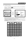
[PLC-SWITCH]
#
1
2
3
5
6
7
8
9
10
11
12
13
14
15
16
PARAM 6. 1/2
#( )
AUTO
RESTART
BLOCK
DELETE
MANUAL
ABS
OPTIONAL
STOP
AUTO
POWER OFF
CHIP CNVR
MANL
CHIP CNVR
AUTO
PLC-SW
LOC-VAR MENUCOM-VAR
MACRO INTERRUPT
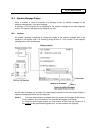
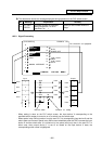
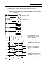
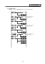
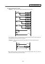
· When setting is done on the PLC switch screen, the input device X corresponding to the
specified switch number is turned on or off to switch over the switch state.
· When special relay SM is turned on from the user PLC, its corresponding input device X and the
switch state are reversed. Special relay SM is reset immediately after the CNC reverses the input
device X and the switch state. It is turned on by one pulse (scan) only also in the user PLC. In
either case, when output device Y is set to on based on the input device X state, the
corresponding switch name is highlighted.