3. Input/Output Signals
- 9 -
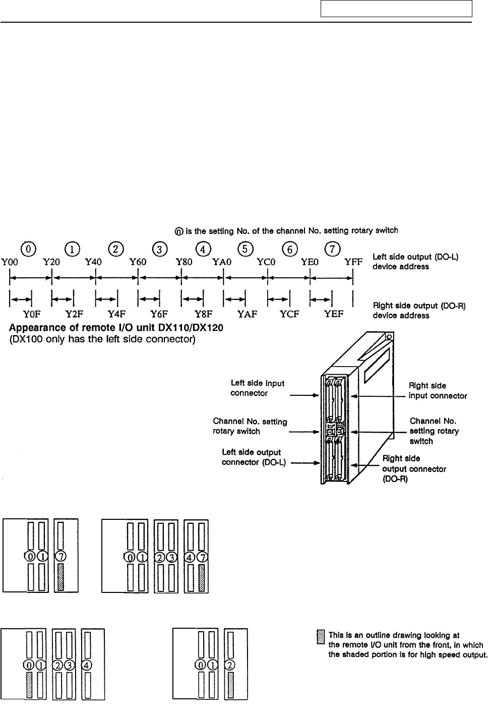
(Usage example 1) Avoid interference with the main process by assigning 7 (last channel) for the
channel No. rotary switch for high speed processing output.
For example, use YE0 to YFF (for 32-point DO-L) or YE0 to YEF (for 16-point
DO-R) as the high speed processing output.
(Refer to <Usage examples 1-1, 1-2 and 1-3> below.)
(Usage example 2) Assign Y0 to Y1F (32-point) for high speed processing, and use Y20 and
following for the main process.
(Refer to <Usage example 2> below.)
(Usage example 3) Assign the device after the device used for main processing for the high speed
process.
For example, if the devices up to Y2D are used for the main process, use Y40 to
Y5F (channel No. setting rotary switch No.: 2) for the high speed process.
(Refer to <Usage example 3> below.)
Relation of channel No. setting switch and device No.
<Usage example 1-2><Usage example 1-1>
(Devices are YE0
and following)
Usage examples 1-2 show the
assignment for the 16-point unit
as the No. of high speed output
points is relatively low.
DX35*/45* DX110/120DX35*/45* DX100
<Usage example 3><Usage example 2>
DX35*/45* DX100 DX100
/120
DX35*/45* DX100


