


89
Reference Manual
IP2030/RM, Rev AA
Section 4: Getting started
June 2014
Section 4: Getting started
P498 No Activity RL (Factory default is 00000)
Select relays for the relay inactivity monitoring operation
Each digit represents a relay. Relay RL1 is selected for monitoring by editing the first
digit to be a “1”. Similarly, relay RL5 is selected with the fifth digit. To de-select a relay,
change the appropriate digit back to a “0”
Rising Level alarm
(Special alarm – see Table 4-5 on page 73 for a full list of auxiliary relay functions)
Menu: SETUP / [CONTROLLER /] APPLICATION / ALARM
P490 R Lev alrm del (Factory default is 0:00 m:s)
The Rising Level alarm requires a minimum of one Assist or Standby mode relay.
If any Standby relay is energized, monitoring of the rising level is activated. For Assist
relays, they must all be energized for monitoring of the rising level to be activated.
A timed delay (P490) starts after the monitoring is activated. If the level is still rising
after the delay time has expired and the calculated rate of change of the control unit PV
(D800) is positive, the result is a Rising Level alarm condition. The alarm condition stops
as soon as the rate of change is negative, indicating a falling level.
For the Rising Level alarm to be indicated by a relay output or the current output, a
method must be selected. See “Set-up alarms” on page 91
See also “Rate of Change mode relay” on page 83
Pump Efficiency alarm (Mobrey MCU901 and MCU902 only)
(Special alarm – see Table 4-5 on page 73 for a full list of auxiliary relay functions)
The pump efficiency feature allows an alarm to be indicated (P550, P4*1) if the calculated
pump efficiency falls below a defined limit (P495).
Menu: SETUP / [CONTROLLER /] APPLICATION / ALARM
P495 Pump effy limit (Factory default is 0% = OFF)
It is an alarm condition while the calculated pump efficiency is below the limit defined
by P495. The pump efficiency calculation is based on the rate of change of the control
unit PV (D800) and is independently monitored for each selected relay (P496)
Pump efficiency values for relays are saved in D861 to D864, located in the MONITOR
menu. See also “Health checking the MCU900 Series control unit” on page 110.
P496 Pump effy RL (Factory default is 0000)
Select relays for pump efficiency limit monitoring operation
Each digit represents a relay. Relay RL1 is selected by editing the first digit to be a “1”.
Similarly, relay RL4 is selected with the fourth digit. (Relay RL5 does not support this
feature.) To de-select a relay, change the appropriate digit to a “0”
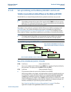
Pump efficiency (PE) is calculated using the rate of change (RoC) of the control unit PV while a
relay is energized. The PE value is saved in D86*; the “*” is the number of the relay (1 to 4)