


Reference Manual
IP2030/RM, Rev AA
Section 3: Installation
June 2014
Section 3: Installation16
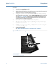
3.4.3 Power connections
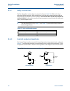
When the control unit is powered by mains alternating current (ac) power, select the voltage as
115V or 230V using the voltage-selector slide switch.
When the control unit is direct current (dc) powered, ensure the supply is adequate (15 to 30
Vdc). Do not exceed 30 Vdc.
A switch or circuit breaker should be installed in close proximity to the instrument, and labelled
as such. Although the Mobrey MCU900 Series control unit meets all European standards for
surge immunity on power and signal lines, it is recommended that lightning suppressors are
also fitted if local conditions make this advisable.
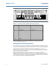
3.4.4 Earthing connections
The IP-rated Mobrey MCU900 Series control unit is double insulated and does not require a
mains earth.
Do not connect terminal 30 to a mains earth. Terminal 30 is provided for use as an intrinsically
safe (or functional) earth connection, which must be used when a transmitter is mounted in a
hazardous area and is connected to terminals 1 and 2.
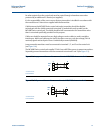
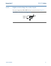
Terminal 3 is to be used for connection of a twisted-pair cable screen (shield) when the control
unit is powering the transmitter (see Figure 3-4 on page 17). This screen (shield) should be left
unconnected at the transmitter end unless there is a terminal provided for this purpose.
When connected to equipment located in a hazardous area, not meeting the requirements of
clause 6.3.12 (Isolation of circuits from earth or frame) in IEC 60079-11:2006
(EN 60079-11:2007), equipotential earthing must be ensured between the equipment and the
intrinsically safe earth. An example of equipotential earthing is a cable with a cross-sectional
area greater than 4 mm
2
and a resistance of less than 1 ohm.
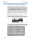
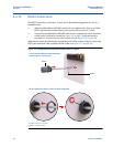
3.4.5 Transmitter connections and cabling
Connection of a transmitter to the control unit does not confer intrinsic safety on the
transmitter. It is the responsibility of the user to ensure any transmitter installed in a hazardous
area is suitable for use and certified accordingly. The installation should be in accordance with a
recognized code of practice.
Check that the electrical parameters of the installed system of control unit, transmitter, any
loop-powered devices, and interconnecting cable to ensure compliance with the product
certificates and technical data. Particular attention must be given to the cable and the
transmitter to ensure that the total capacitance and inductance limits stated in the technical
data in Appendix B: Product Certifications are not exceeded.
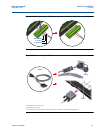
Cable joins are allowable in cabling the transmitter, provided that the joint is made within an
IP20/NEMA 3 (minimum) enclosure suitable for the environment, and that wiring withstands a
test voltage of 500 V r.m.s. to earth.
The maximum length of cable permissible between the transmitter and control unit is
determined by limits imposed by the intrinsic safety certificates of the instruments and control
drawings.