


57
Reference Manual
IP2030/RM, Rev AA
Section 4: Getting started
June 2014
Section 4: Getting started
If the mA signal is not scaled for the full level range of the channel, P114 (or P124) must be
programmed with a value to convert (scale) the mA signal to be a value in the range 0.0 to 1.0.
For example, if the maximum current is below 20 mA for a full channel, say 12 mA,
set P114 = 16 * (12 - 4) = 2.
Setting P114 (or P124) when a HART level transmitter is connected
The maximum level measurement from the HART transmitter must be equal to the height of the
liquid when the channel is full.
The level measurement, after any input offset has been applied, must be re-scaled to the range
0.0 to 1.0 ready for input to the NLP calculation.
For example, if the level measurement range is 0.0 to 1.5 m, set P114 = (1.0 / 1.5) = 0.667
Setting P116 (or P126) to the maximum flow expected in the channel
Finally, parameter P116 (or P126) must be programmed with the maximum flow expected in
the channel, which will occur at the maximum liquid level in the channel.
The control unit Primary/Process Value (D800) for the flow rate is derived by applying the
normalized transmitter input (range 0.0 to 1.0) to the profile, and then converting (scaling) by
parameters P114 and P116 (or P124 and P126).
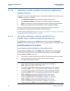
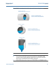
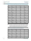
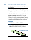
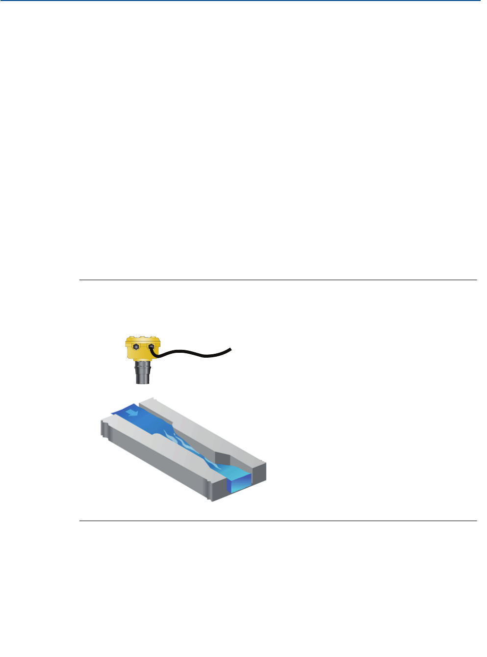
Figure 4-20. Example of a non-linear open channel profile
P113 = “Flume (3/2)” (using 3/2 power law) (To BS3680)
P114 = (1.0 / Maximum height of flow in channel)
P115 = Plotted non-linear profile of channel
P116 = Maximum flow at maximum flow height