140
Reference Manual
IP2030/RM, Rev AA
Appendix E: Support for HART
®
Transmitters
June 2014
Appendix E: Support for HART Transmitters
Some Explosion-proof (Exd) rated transmitters have a high input voltage requirement which can
result in HART communication failing to function at high loop currents. For example, the
Explosion-proof version of the Rosemount 5400 Series transmitter has a minimum input voltage
requirement as follows:
15.5 Vdc at 21.75 mA
20 Vdc at 3.75 mA
The Exd version of Rosemount 5400 Series transmitter would not be suitable for use with the
MCU900 Series control unit.
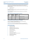
Tabl e E-1 shows the minimum MCU900 terminal output voltage (worst case conditions) for
varying load conditions.
Table E-1. Minimum terminal output voltages from control unit
E.3.2 Universal and common practice commands
Support for the Universal and Common Practice commands of all other HART 5/6/7
transmitters is provided in accordance with HART practice.
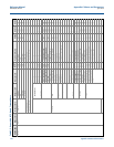
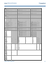
Table C-2 on page 132 shows the menu structure and parameters for generic HART 5/6/7
transmitters parameters as seen on a MCU900 Series control unit or other HART-based devices.
Universal commands
#0 Read unique identifier.
#1 Read primary variable.
#2 Read loop current and percent of range.
#3 Read dynamic variables and loop current.
#6 Write polling address.
#7 Read loop configuration.
#12 Read message.
#13 Read tag, descriptor, date.
#14 Read primary variable transducer information.
#15 Read device information.
#16 Read final assembly number.
#17 Write message.
Load
current
mA
MCU900
terminal
voltage Vdc
Maximum
loop
resistance ohms
3.6 21.0 2370 Minimum fault current
4.0 20.8 2195 Normal minimum output
20.0 13.9 95 Normal maximum output
21 13.6 50 Maximum o/p fault level


