


15
Reference Manual
IP2030/RM, Rev AA
Section 3: Installation
June 2014
Section 3: Installation
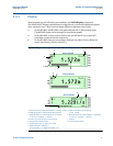
3.4.2 Making electrical connections on panel-mount units
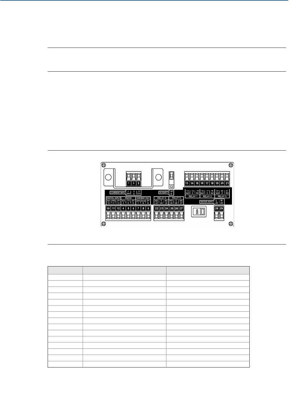
Field wiring connections are made to the back of the panel-mount control unit using the
two-part (plug/socket) terminal connectors provided. Figure 3-3 shows the rear panel layout.
Note
The plug/socket terminal connectors on the panel mount unit are polarized (keyed)
to prevent inter-changeability and incorrect connection.
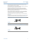
Cabling between the Mobrey MCU900 Series control unit and a transmitter should be a
screened (shielded), twisted-pair type with the cable screen (shield) connected to terminal 3
(marked with earth/ground symbol) on the control unit. The cable screen (shield) should be left
unconnected at the transmitter end unless there is a terminal specifically provided for this
purpose. Cable runs should be separate from any high voltage or mains cables to avoid crosstalk
or interference.
Connect terminal 30 (intrinsically safe earth/ground) to a high integrity earth/ground point if
the transmitter connected to terminals 1 and 2 is sited in a hazardous area.
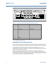
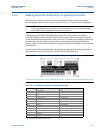
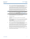
Figure 3-3. Connection terminals layout (for mains-powered panel-mount unit)
(The direct current (dc) powered unit has a slightly different layout – terminals 31 and 32 replace terminals 28 and 29).
Table 3-2. Connection descriptions for panel mount unit
Terminal Function Terminal marking
1 Loop supply 24V
2 Current input Iin
3 Cable screen Earth (Earth symbol)
4-6 RS232 RX-TX-0V
7-9 Current output 24V-Iout-0V
10-12 Digital input 1 and 2 IN1-IN2-0V
13-15 Relay 1 NO-COM-NC
16-18 Relay 2 NO-COM-NC
19-21 Relay 3 NO-COM-NC
22-24 Relay 4 NO-COM-NC
25-27 Relay 5 NO-COM-NC
28-29
(1)
(1) Mains-powered control unit only.
Mains input L-N
30 I.S. Earth (Earth symbol)
31
(2)
(2) Direct current (dc) powered control unit only.
Negative -
32
(2)
Positive +