


17
Reference Manual
IP2030/RM, Rev AA
Section 3: Installation
June 2014
Section 3: Installation
No other outputs from the control unit must be routed through a hazardous area unless
protected by an additional I.S. Barrier (not supplied).
It is the responsibility of the user to ensure that any transmitter is installed in accordance with
the manufacturer’s instructions supplied with the transmitter.
Cable between the MCU900 Series control unit and a transmitter should be shielded
twisted-pair with the shield connected to terminal 3 (marked with earth symbol) on the
MCU900 Series control unit. The shield should be left unconnected at the transmitter unless
there is a terminal specifically provided for this purpose.
Cable runs should be separate from any high voltage or mains cables to avoid crosstalk or
interference. Multi-core cable may be used if the other cores carry only low voltage (24 Vdc
nominal) signals and each pair of cores is individually screened (shielded).
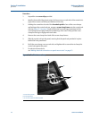
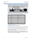
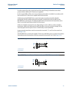
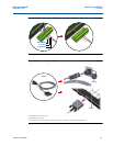
Loop-powered transmitters must be connected to terminals 1, 2, and 3 on the control unit
(see Figure 3-4).
The MCU900 Series control unit supplies 23 Vdc from a 400 Ohm source to power transmitters.
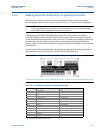
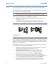
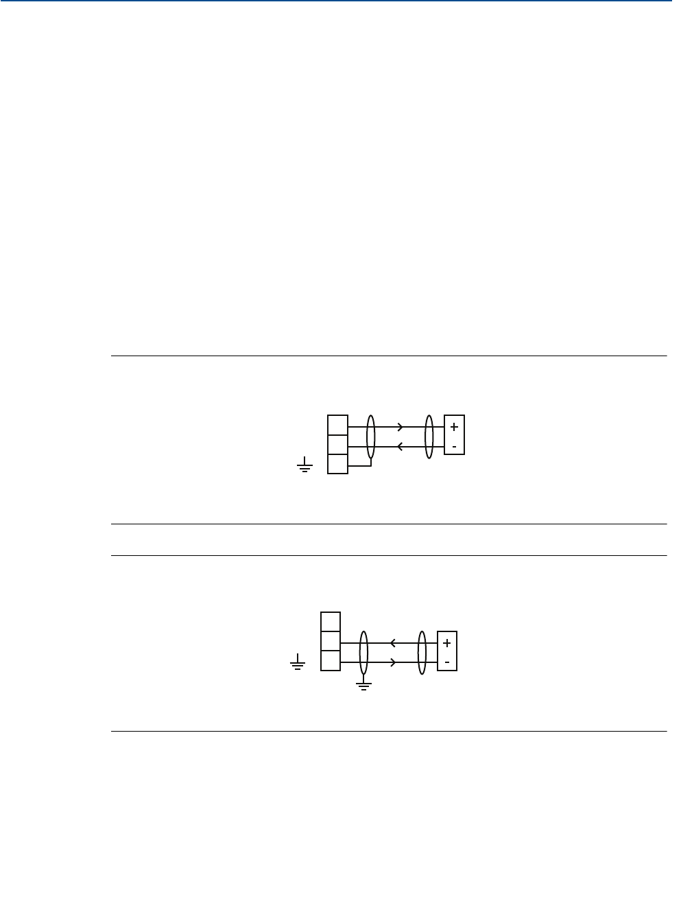
Separately powered transmitters must be connected to terminals 2 and 3 (see Figure 3-5).
Figure 3-4. Loop-powered transmitter connections to MCU900 Series control unit
A. Control unit
B. Transmitter
Figure 3-5. Self-powered transmitter connections to MCU900 Series control unit
A. Control unit
B. Transmitter
1
2
3
A
B
24 V
I
IN
1
2
3
1
2
3
A
B
24 V
I
IN