


Reference Manual
IP2030/RM, Rev AA
Section 3: Installation
June 2014
Section 3: Installation14
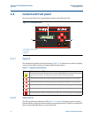
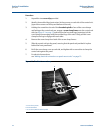
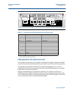
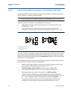
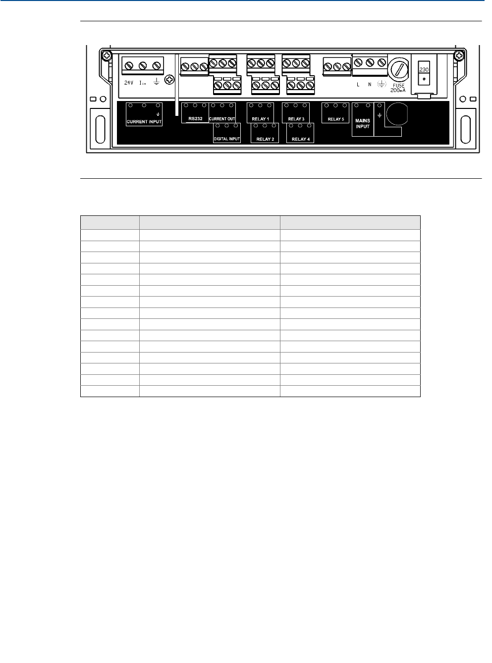
Figure 3-2. Connection terminals layout (for mains-powered wall-mount unit)
(The direct current (dc) powered unit has a slightly different layout – terminals 31 and 32 replace terminals 28 and 29).
Table 3-1. Connection terminal descriptions (for wall-mount unit)
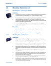
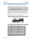
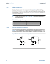
Cable glands for the wall-mount unit
The five cable-entry positions are pre-drilled to accept M20 cable glands. The Mobrey MCU90F
control unit has a data download socket factory pre-fitted in one of these cable-entry positions.
Two cable glands, rated IP65 and suitable for cable with outside diameter 4 to 7 mm, are
supplied for use with the mains supply and transmitter cable. M20 blanking plugs are supplied
for the other three cable entry positions.
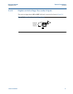
All glands and blanking plugs are supplied in a plastic bag. The installer must fit these, or
suitable equivalents, in place of the transit red-caps, to ensure weatherproofing of the control
unit. The white sealing washers supplied with the cable glands and blanking plugs must be fitted
on the outside of the enclosure under gland/blanking plug.
Terminal Function Terminal marking
1 Loop supply 24V
2 Current input Iin
3 Cable screen Earth (Earth symbol)
4-6 RS232 RX-TX-0V
7-9 Current output 24V-Iout-0V
10-12 Digital input 1 and 2 IN1-IN2-0V
13-15 Relay 1 NO-COM-NC
16-18 Relay 2 NO-COM-NC
19-21 Relay 3 NO-COM-NC
22-24 Relay 4 NO-COM-NC
25-27 Relay 5 NO-COM-NC
28-29
(1)
(1) Mains-powered control unit only.
Mains input L-N
30 I.S. Earth/Ground (Earth/Ground symbol)
31
(2)
(2) Direct current (dc) powered control unit only.
Negative -
32
(2)
Positive +
10 11 12
0VIN2IN1
789
24V
I
out
0V
456
RX TX
0V
13
16
14
17
15
18
NO COM NC
NCCOMNO
25 26 27
NO
COM
NC
19
22
20
23
21
24
NOCOM NC
NCCOMNO
1
24V
I
in
2 3
FUSE
200mA (T)
28
L
N
29 30
IS EARTH