


83
Reference Manual
IP2030/RM, Rev AA
Section 4: Getting started
June 2014
Section 4: Getting started
P563 Digital Input (Factory default setting is None)
Fault relay de-energizes while digital input IN1 or IN2 is triggered and the option is
Both or Relay
See “Digital inputs IN1 and IN2” on page 63 for how to select the Fault action required
for this feature
Note
Faults can be indicated using the output current if the Current or Both options are
selected (see “Set-up the current output” on page 68)
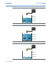
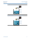
PV Limits mode relay
Menus:
SETUP / [CONTROLLER /] OUTPUT / RELAY / RELAY 1, / RELAY 2, etc.
This relay mode uses the relay On Point and Off Points (e.g. P411 and P412) as high and low
limit alarms for the control unit PV value (D800). The points can be in any order of value.
The relay is energized while the PV value exceeds the higher limit point value or while it is below
the lower limit point value.
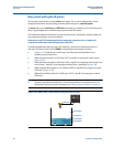
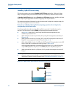
Rate of Change mode relay
Menus:
SETUP / [CONTROLLER /] OUTPUT / RELAY / RELAY 1, / RELAY 2, etc. and
MONITOR / [CONTROLLER /] READINGS / Rate of Change
A rate of change value for the control unit PV value (D800) is calculated every 5 seconds in units
of PV per minute:
D809 = (PV
now
- PV
5 seconds ago
) * 12
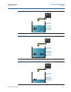
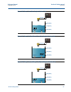
The On and Off points of a Rate of Change (RoC) mode relay are used as high and low limits for
read-only parameter D809. Limit values are in units of PV per minute (PV/min) and can be in any
order of value. The relay is energized while D809 exceeds the higher limit value or falls below the
lower limit value.
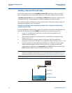
Typically, where the PV value is a liquid level measurement, the RoC relay can be used to warn of
a quickly rising or falling liquid level. Alternatively, the RoC mode relay can be used for
controlling the rate of liquid flow.
For further uses of D809, see “Pump Efficiency alarm (Mobrey MCU901 and MCU902 only)” on
page 89 and “Pumped volume totalizing” on page 90.