


Reference Manual
IP2030/RM, Rev AA
Section 4: Getting started
June 2014
Section 4: Getting started72
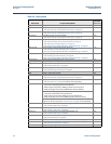
Table 4-4. Relay modes
Relay Mode Purpose of Relay Mode
Auxiliary
functions
(Table 4-5)
None Relay is not used No
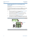
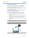
Set point SV On/Off Point control using SV (D801)
– see “How to set-up an on/off point control relay” on page 70.
Yes
Set point TV On/Off Point control using TV (D802)
– see “How to set-up an on/off point control relay” on page 70.
Yes
Set point FV On/Off Point control using FV (D803)
– see “How to set-up an on/off point control relay” on page 70.
Yes
Assist Duty Assist, On/Off Point Control and Auto Sequence
– see “Duty Assist relay with common off points” on page 74.
– see “Duty Assist with split off points” on page 76.
– see “Auto-sequence (Mobrey MCU901 and MCU902 only)” on page 84.
Yes
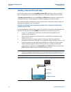
Stby com off Duty Standby, Common Off and Auto Sequence
– see “Standby, Common Off mode relay” on page 78
– see “Auto-sequence (Mobrey MCU901 and MCU902 only)” on page 84.
Yes
Stdby split off Duty Standby, Split Off and Auto Sequence
– see “Standby, Split Off mode relay” on page 80.
– see “Auto-sequence (Mobrey MCU901 and MCU902 only)” on page 84.
Yes
Digital Input 1 Relay energizes while Digital Input 1 (IN1) is active. Yes
Digital Input 2 Relay energizes while Digital Input 2 (IN2) is active. Yes
Sampler Relay outputs sampler pulses
– see “Sampler mode relay” on page 82.
No
RoC Relay is energized if the rate of change of the control unit PV is out-of-limits
– see “Rate of Change mode relay” on page 83.
Yes
Digital input 1+2 Relay is energized while Digital Input 1 (IN1) and 2 (IN2) are both active Yes
Off Relay is always de-energized No
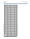
Set Point On/Off Point Control using PV (D800)
– see “How to set-up an on/off point control relay” on page 70.
Yes
Alarm Relay is allocated to alarm indication duty
– see “Set-up alarms” on page 91 for details of alarm handling.
Yes
Hi or Lo Alarm High alarm limit (using On/Off Point Control):
– The On Point must be greater than the Off Point.
– Relay energizes when the PV (D800) is greater than the On Point.
– Relay de-energizes when the PV (D800) is less than the Off Point.
Yes
Low alarm limit (using On/Off Point Control):
– The On Point must be less than the Off Point.
– Relay energizes when the PV (D800) is less than the Off Point.
– Relay de-energizes when the PV (D800) is greater than the On Point.
An “A” is shown by the RL1 icon status (on the Full PV Display) when there is a
high or low alarm. (The section “Set-up alarms” on page 91 is not applicable).
Totalizer Relay outputs totalizer pulses (MCU901 only)
– see “Totalizer mode relay” on page 82.
No
Totalizer 1 Relay outputs totalizer 1 pulses (MCU902/MCU90F only)
– see “Totalizer mode relay” on page 82.
No
Totalizer 2 Relay outputs totalizer 2 pulses (MCU902/MCU90F only)
– see “Totalizer mode relay” on page 82.
No
Fault Indicate fault condition by de-energizing relay
– see “Fault mode relay” on page 82.
No
Custom To set-up a custom relay operation, see “Custom mode relay” on page 86. No
PV limits Relay energizes while control unit PV value (D800) is within on/off point limits.
– see “PV Limits mode relay” on page 83.
Yes
On Relay is always energized No