


Reference Manual
IP2030/RM, Rev AA
Section 3: Installation
June 2014
Section 3: Installation20
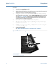
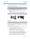
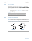
3.4.7 Relay connections
The five voltage-free contact relays are grouped as shown in Tab le 3 -3 . Whilst each relay is
individually double-insulated, their arrangement is such that the insulation between relays in
the same group is standard or ‘basic’ insulation. Care must be taken in order to avoid the risk
of electric shock. It is allowed to use relays in the same group to control circuits with both mains
and dc, or low voltage circuits.
Note
The relay labels (NO-C-NC) in Ta bl e 3 -1 and Tab le 3 -2 represent the relay terminals in
the de-energized state.
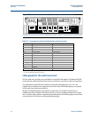
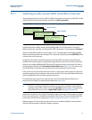
Table 3-3. Relay configuration groups
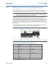
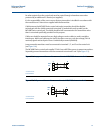
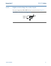
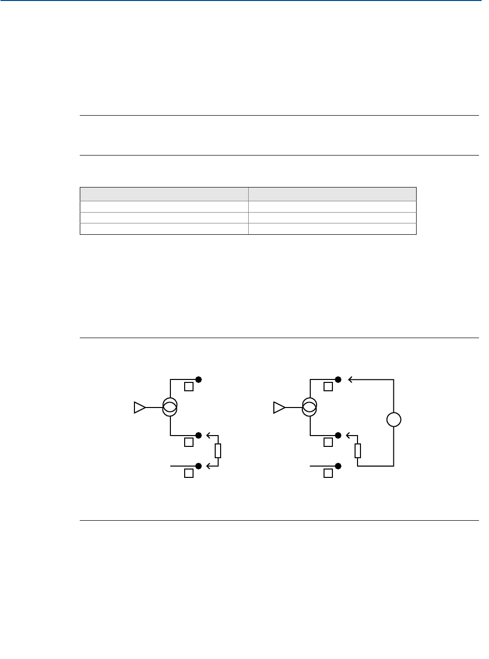
3.4.8 Current output connections
The Current Output may be connected in internally-powered or loop-powered mode, as shown in
Figure 3-7. In loop-powered mode, an external power source is required. A minimum of 2.5 V dc
is required across terminals 7 and 8 for correct operation. The voltage must not exceed 30 Vdc.
Figure 3-7. Alternative output current configurations
Wall Mount MCU900 Series control unit Panel Mount MCU900 Series control unit
Relay 1 and 2: Group 1 Relay 1, 2 and 3 : Group 1
Relay 3 and 4 : Group 2 Relay 4 and 5 : Group 2
Relay 5: Group 3
7
8
9
0V
Io
24V
Load
+
-
7
8
9
0V
Io
24V
Load
External
Supply
+
+
-
-
Internally Powered Loop Powered