


7
Reference Manual
IP2030/RM, Rev AA
Section 2: Control Unit Overview
June 2014
Section 2: Control Unit Overview
2.4.3 Display
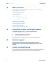
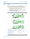
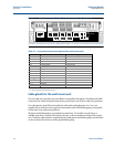
After the power-up and self-checks are completed, the Full PV Display is presented.
The default Full PV Display typically features a digital clock, a measured variable with display
units, and status icons. There are some display differences between control units:
On the MCU901 and MCU902, a bar graph indicates the 4–20mA output signal.
(The MCU90F display can be changed to show the bar graph).
On the MCU902, an extra icon on the first line and indicates if one or two HART
transmitters connected to the control unit.
On the MCU90F, there are two totalizers displayed; one above and one below the
control unit Primary / Process Value (PV).
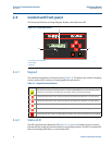
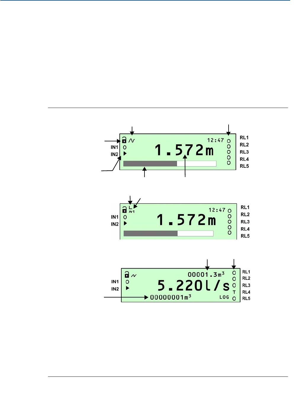
Figure 2-4. Typical displays of the MCU901, MCU902, and MCU90F
A. Program/Run App mode (locked padlock = Run App mode) H. HART Transmitter Communicating
B. HART Transmitter Communicating (absent if Idle) (1=Tx1, 2=Tx2)
C. Relay (RL) Status: O = De-energized,
= Energized, I. Relay (RL) Status: O = De-energized,= Energized,
A = Alarm, S = Sampler, T = Totalizer A = Alarm, S = Sampler, T = Totalizer
D.Primary / Process Value (PV) of Control Unit J. Totalizer 1
E. Bar graph of 4–20mA Output K. Totalizer 2 (Daily Total)
F. Digital Input Status: O = Open,
= Closed
G. HART Transmitter Allocated:
Left Vertical Bar = Tx1; Right Vertical Bar = Tx2
Mobrey MCU901
Mobrey MCU902
B
D
E
A
C
F
G
H
K
I
J
Mobrey MCU90F