


13
Reference Manual
IP2030/RM, Rev AA
Section 3: Installation
June 2014
Section 3: Installation
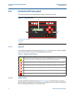
3.4 Electrical installation
3.4.1 Making electrical connections on wall-mount units
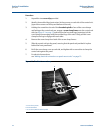
All field wiring connections are accessible by removing the lower terminal cover, which is
secured by two screws on the wall-mount control unit.
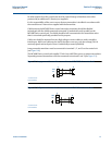
The cabling between the Mobrey MCU900 Series control unit and a transmitter should be a
screened (shielded), twisted-pair type with the cable screen (shield) connected to terminal 3
(marked with earth/ground symbol) on the Mobrey MCU900 Series control unit. The cable
screen (shield) should be left unconnected at the transmitter end unless there is a terminal
specifically provided for this purpose.
Cable runs should be separate from any high voltage or mains cables to avoid crosstalk or
interference.
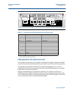
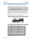
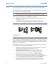
Figure 3.4.2 on page 15 shows the layout of the control unit terminals. All terminal blocks are
suitable for wires 14 to 26 AWG (0,5 to 1,5 mm
), except the mains terminals which are suitable
for wires 10 AWG (2,5 mm
). Insulation should be stripped back
1
/4 in. (7 mm).
Transmitter connections are made on the left side of the terminals enclosure. The intrinsically
safe earth/ground (terminal 30) must be connected to a high integrity earth/ground point if the
transmitter connected to terminals 1 and 2 is sited in a hazardous area.
Note
Use only 167 F (75 C) copper conductors for field wiring.
Note
In intrinsically safe systems, apparatus connected to the MCU900 Series control unit
must not be supplied from a voltage greater than 250V r.m.s. or 250 Vdc.
It is the responsibility of the installer to:
Refer to safety data and electrical specifications in Appendix A: Reference Data
Refer to the certifications and control drawings in Appendix B: Product Certifications
Check and obtain any work permits required before applying power to the unit
Observe all local regulations and approval requirements
Ensure the wiring is suitable for the load current
Ensure the wiring insulation is suitable for the voltage, temperature, and environment
of the installation
Ensure suitable cable glands or conduit connections are used when wiring to the
control unit to maintain enclosure integrity
Never remove or modify the mechanical barriers separating the terminal area from the
main enclosure and separating the transmitter input terminals from other terminals.