


100
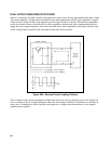
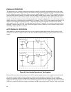
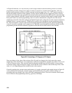
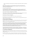
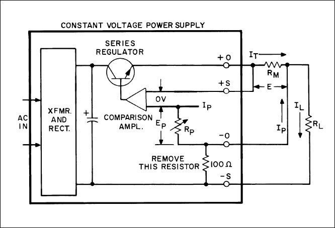
As Figure 69 indicates, it is only necessary to add a single external current monitoring resistor to a remote
programming constant voltage power supply in order to convert it to constant current operation. (Also any
remote sensing protection resistor or diode connected inside the supply from –S to - OUT must be removed.)
Because the proper operation of the regulator circuitry requires that the positive output and positive sensing
terminals be at nearly the same potential, the external current monitoring resistor RM must be connected to the
positive output terminal, while the constant current load must be connected to the negative output terminal. The
front panel control (or remote programming control) is used to determine the voltage E across the current
monitoring resistor R
M
. Since this voltage E will be held equal to the voltage E
P
across the control resistance by
feedback action, a constant current I
T
= E/RM will be caused to flow through the current monitoring resistor
R
M
. The load current I
L
consists of the current flowing through the monitoring resistor plus the programming
current I
P
(normally negligibly small compared to I
T
). Both the current through the monitoring resistor and the
programming current are held constant by regulator action; thus the net load current is also constant.
Figure 69. Converting a CV Supply to CC Output
Since any change in the value of the resistance R
M
will result in a change in the load current, the current
monitoring resistor should have a low temperature coefficient and should be operated at less than 1/10 (or even
1/100) of its power rating . This, plus the restriction that the total IR drop across R
M
and R
L
in series cannot
exceed the voltage rating of the power supply, means that R
M
will be selected so that its IR drop will be of the
order of 1 volt, depending upon the constant current value required.
Generally speaking, the constant current performance of a supply connected in the method shown in Figure 69
can be predicted by dividing the constant voltage specification by the value of R
M
, and then adding on a
percentage basis any change in the value of R
M
due to temperature effects. The lowest constant current output
level is limited to the programming current I
P
, typically 5 milliamps.