


61
Autotransformers
An autotransformer (or isolation transformer) connected between the ac power source and the power supply
input terminals should be rated for at least 200% of the maximum rms current required by the power supply.
Because a power supply input circuit does not draw current continuously, the input current wave is not
sinusoidal, and the peak-to-rms ratio is generally greater than √2, and can be as high as two or more at full
output. To avoid autotransformer saturation and consequent limiting of peak input current, the autotransformer
must have a rating higher than suggested by the power supply's rms input current. Failure to follow this
precaution may result in the power supply not meeting its specifications at full output voltage and current.
The autotransformer common terminal should be connected to the acc (not ac) terminals of both the power
supply and the input power line. If acc is not connected to the common terminal of the autotransformer, the
input acc terminal of the power supply will have a higher than normal ac voltage connected to it, contributing to
a shock hazard and, in some cases, greater output ripple.
Line Regulators
Most ac input line regulators should not be used with regulated power supplies without first checking with the
power supply manufacturer. Such regulators tend to increase the impedance of the line in a resonant fashion,
and can cause malfunctioning of power supplies particularly if they employ SCR or switching type regulators or
pre-regulators. Moreover, since the control action of the most common line voltage regulators is accompanied
by a change in the output waveshape, their advantage in providing a constant rms input to a power supply is
small. Often these waveshape changes are just as effective in causing output voltage changes of the power
supply as the original uncorrected line voltage amplitude changes.
Input AC Wire Rating
When connecting ac to a power supply, it is necessary to use a wire size which is rated to carry at least the
maximum power supply input current. In addition, a check should be made to determine whether a still larger
wire size will be required to retain a sufficiently low impedance from the service outlet to the power supply
input terminals, particularly if a long cable is involved.
As an extreme example, many power supplies would fail to function properly if the IZ drop in the input cable
approached 10% of the line voltage even though the wire size had an adequate current rating, and even though
the voltage at the power supply terminals was not below the rated input range specified by the manufacturer.
As a general guideline, input cables should employ wire size sufficient to insure that the IZ drop at maximum
rated power supply input current will not exceed 1% of the nominal line voltage.
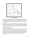
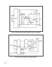
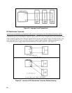
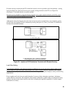
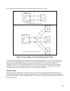
LOAD CONNECTIONS FOR ONE POWER SUPPLY
The simplest (and most common) example of improper load wiring is illustrated in Figure 34. Each load sees a
power supply voltage which is dependent upon the current drawn by the other loads and the IZ drops they cause
in some portion of the load leads. Since most power supply loads draw a current which varies with time, a
time-varying interaction among the loads results. In some cases this interaction can be ignored, but in most
applications the resulting noise, pulse coupling, or tendency toward inter-load oscillation is undesirable and
often unacceptable.